Polishing device for welding tip

a technology of polishing device and welding tip, which is applied in the direction of cooling electrodes, electrode maintenance, manufacturing tools, etc., can solve the problems of requiring significant man-hours and requiring workers' operation, and achieve the effect of reducing the cost of polishing work, simple configuration and simplified welding work

Active Publication Date: 2020-03-26
TOYOTA JIDOSHA KK
View PDF1 Cites 2 Cited by
  • Summary
  • Abstract
  • Description
  • Claims
  • Application Information

AI Technical Summary

Benefits of technology

[0013]According to the disclosure, the polishing work on the welding tip can be...

Problems solved by technology

However, such a method requires the worker...

Method used


Image

  • Polishing device for welding tip
  • Polishing device for welding tip
  • Polishing device for welding tip

Examples


Embodiment Construction

[0034]Hereinafter, a detailed description will be provided on an embodiment of the disclosure, with reference to the drawings. It should be noted that the disclosure is not limited to the following embodiment. In addition, for a purpose of clarifying the description, the following description and the drawings will be appropriately simplified.

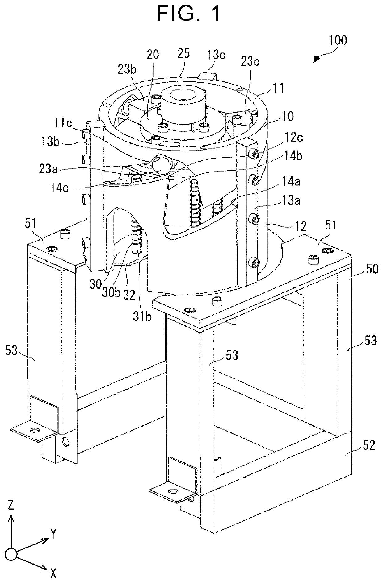
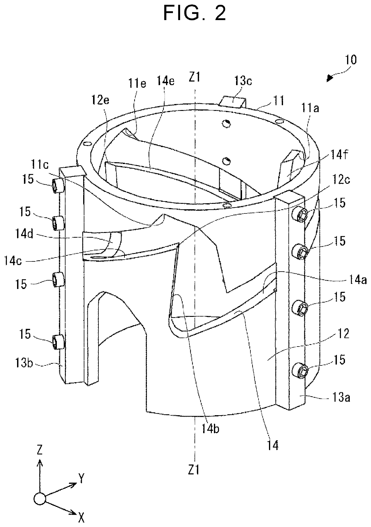
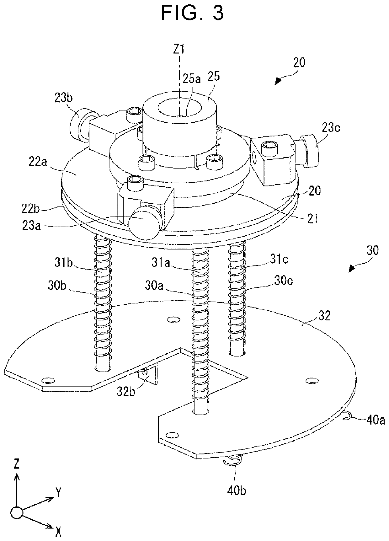
[0035]A description will be provided on a first embodiment with reference to FIG. 1 to FIG. 6. It should be noted that right-handed X, Y, Z coordinates illustrated in FIG. 1 and other drawings are provided to illustrate positional relationships among components. In general, a direction toward a positive side on a Z-axis is a vertically upward direction, an X-Y plane is a horizontal plane, and these are common in the drawings. FIG. 1 is a perspective view of a polishing device according to the first embodiment. FIG. 2 is a perspective view of a holder of the polishing device according to the first embodiment. FIG. 3 is a perspective view of a pol...


PUM

PropertyMeasurementUnit
Distanceaaaaaaaaaa
Circumferenceaaaaaaaaaa

Abstract

A polishing device for a welding tip includes a cylindrical holder; and a polishing unit. The polishing unit includes a blade configured to polish a welding tip. The blade polishes the welding tip due to rotation of the polishing unit. The holder includes a groove extending along an entire inner circumference of the holder. The groove includes axial groove portions each of which extends along an axis of the holder, and inclined groove portions each of which extends for a specified first distance and is inclined in one direction with respect to the axial groove portions. The axial groove portions and the inclined groove portions are alternately arranged. The polishing unit includes projected portions each of which extends to an inside of the groove, and the number of the projected portions is two or more and is equal to or less than the number of the axial groove portions.

Description

INCORPORATION BY REFERENCE[0001]The disclosure of Japanese Patent Application No. 2018-176920 filed on Sep. 21, 2018 including the specification, drawings and abstract is incorporated herein by reference in its entirety.BACKGROUND1. Technical Field[0002]The disclosure relates to a polishing device for a welding tip.2. Description of Related Art[0003]There is a polishing device for a welding tip that polishes a welding tip by rotating one of the welding tip and a blade while the welding tip and the blade are in contact each other. An example of such a polishing device is disclosed in Japanese Patent Application Publication No. 7-144285 (JP 7-144285 A).SUMMARY[0004]The inventors of the present application have found the following problems on such a polishing device for a welding tip. The polishing devices for a welding tip often require an actuator used to rotate the welding tip or the blade, in addition to an actuator used for causing the translational motion of the welding tip. Thus...

Claims


Application Information

Patent Timeline
IPC IPC(8): B24B19/16B23K11/30
CPCB23K11/3063B24B19/16B23P23/04B23Q3/062B23K11/3054B23B5/166
Inventor IWANO, YOSHIHIROKANAKUBO, RYOSANDA, SHOUGO
Owner TOYOTA JIDOSHA KK
Why Eureka
Try Eureka