
Assembled double steel-concrete composite shear wall embedded with damping interlayer and method for mounting same

Active Publication Date: 2020-03-26
ZHANG CHUNWEI
View PDF16 Cites 2 Cited by
  • Summary
  • Abstract
  • Description
  • Claims
  • Application Information

AI Technical Summary

Benefits of technology

The invention aims to address the shortcomings of traditional double steel-concrete composite shear walls by incorporating an damping interlayer. This results in better control of slipping between the steel plates and concrete, as well as better damping and energy dissipation ability, leading to improved seismic performance and resistance to explosions and impacts. Additionally, the invention is easy to assemble, disassemble, and avoids defects in the steel plates and grout leakage after concrete pouring.

Problems solved by technology

However, existing double steel-concrete composite shear walls are mainly cast in site and are weak in energy dissipation, which means the double steel-concrete composite shear wall will deform easily to consume energy when an earthquake comes.
It is time-consuming and costly to either repair the wall or replace the steel plate.
The viscoelastic damping wall is an energy-consuming member with steel plates outside and a damping material inside, but it cannot function as a bearing.
After an earthquake, the double steel-concrete composite shear wall tends to deform to consume energy.
Thus, such shear wall needs to be repaired when it is not seriously deformed, and when there is a serious deformation, the steel plates of the shear wall should be replaced because they cannot be repaired.
Moreover, most double steel-concrete composite shear walls are cast in place, which makes it time-consuming and costly to either repair the wall or replace the steel plates.
In addition, defects of initial bending and eccentricities cannot be greatly avoided when the double steel-concrete composite shear wall adopts thin or ultrathin steel plates.

Method used


Image

  • Assembled double steel-concrete composite shear wall embedded with damping interlayer and method for mounting same
  • Assembled double steel-concrete composite shear wall embedded with damping interlayer and method for mounting same
  • Assembled double steel-concrete composite shear wall embedded with damping interlayer and method for mounting same

Examples


example 1

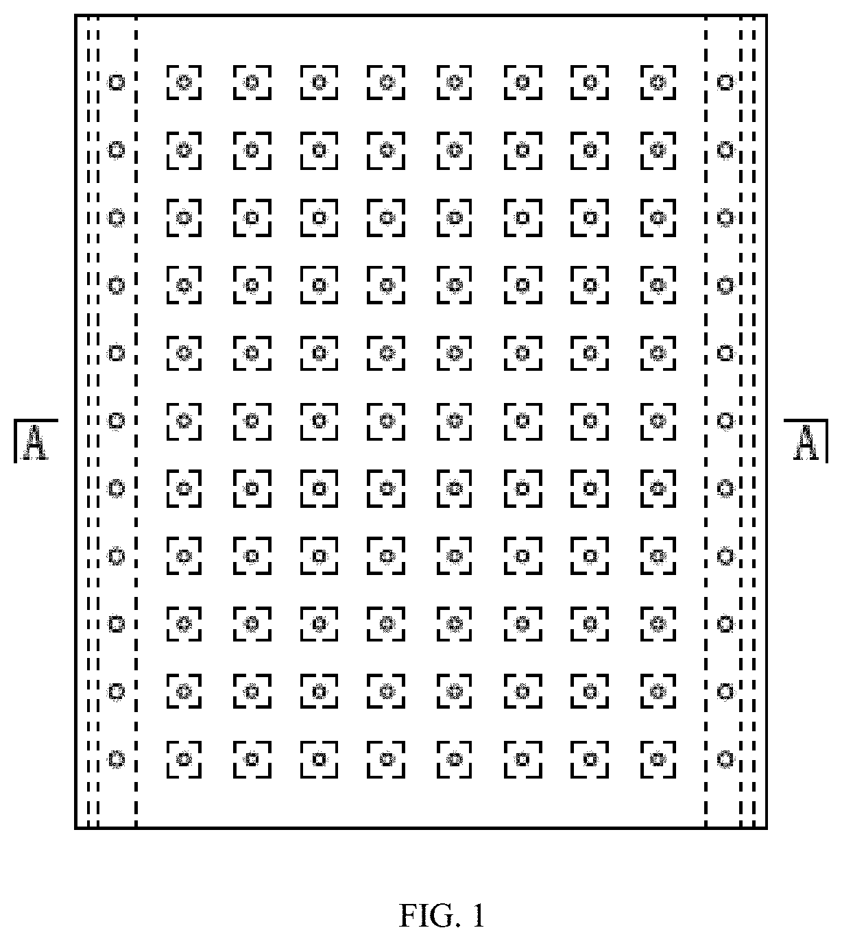
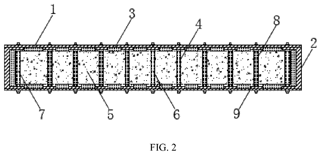
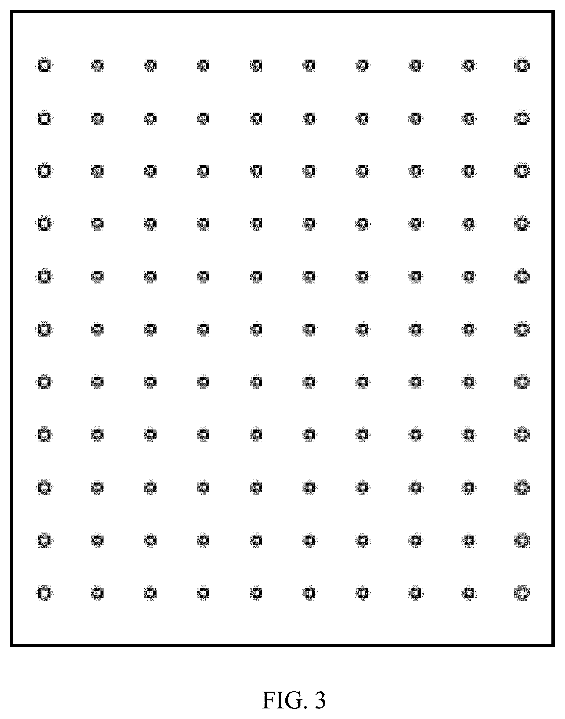
[0047]As shown in FIGS. 1-8, the invention provides an assembled double steel-concrete composite shear wall embedded with a damping interlayer, including a double steel layer, a double damping interlayer and a concrete layer. The shear wall is formed by bolted bar joints. First steel plates, a first damping interlayer and the concrete layer are provided sequentially from an outer side to an inner side, forming a symmetrical wall structure. The double steel layer includes two first steel plates 1 which are arranged along a length of the assembled double steel-concrete composite shear wall in a parallel manner and two second steel plates 2 located at a section of the first steel plates along a width of the assembled double steel-concrete composite shear wall. The double damping interlayer includes a first damping interlayer 3 which locates between the first steel plates and a concrete layer 5 and a second damping interlayer 4 which surrounds the bolted bar joints and is surrounded by ...

example 2

[0052]This embodiment is similar to Example 1 except for the following technical features. The first damping layer is embedded between the first steel plates, the second steel plates and the concrete layer, and is made of aluminum foam materials, the high porosity and energy absorption thereof enhance the out-of-plane explosion and impact resistance of the wall. The second damping interlayer is still made of high damping rubber materials and is embedded between the concrete layer and the binding bar component with support plates to realize the shear slipping of the damping layer together with the first damping layer.

[0053]Example 2 is mainly employed when the wall requires high explosion and impact resistance. Similarly, other material types can also be employed, and the hole of the first damping interlayer can also be other shapes, such as a triangle, a circle, etc., to show the unique material properties, such as sound insulation, radiation attenuation, vibration reduction, etc.

example 3

[0054]The invention provided a method for mounting the assembled double steel-concrete composite shear wall embedded with a damping interlayer, which is specifically described as follows.

[0055]a) An adhesive is respectively applied onto the two first steel plates, the two second steel plates and the first damping interlayer; the two first steel plates are firmly bonded with the first damping interlayer, and the two second steel plates are firmly bonded with the first damping interlayer.

[0056]b) The second damping interlayer is respectively bonded to the binding bar component with support plates and the high-strength binding bar component, and then is respectively covered with the steel tube.

[0057]c) The high-strength binding bar component at both sides of the wall is mounted and fixed to stabilize each component of the wall.

[0058]d) An adhesive is respectively applied onto the support plates; the support plates are placed in the hole of the first damping layer to firmly bond the fir...


PUM


Abstract

This invention relates to architecture techniques, and more particularly to an assembled double steel-concrete composite shear wall embedded with a damping interlayer, which includes a double steel layer, a double damping interlayer and a concrete layer. The shear wall is formed by bolted bar joints. The double steel layer includes two first steel plates which are arranged along a length of the assembled double steel-concrete composite shear wall in a parallel manner and two second steel plates along a width of the assembled double steel-concrete composite shear wall. The double damping interlayer includes a first damping interlayer which locates between the first steel plates and the concrete layer and a second damping interlayer which surrounds the bolted bar joints and is surrounded by a steel tube.

Description

CROSS-REFERENCE TO RELATED APPLICATIONS[0001]This application is a continuation of International Application No. PCT / CN2019 / 094543 with a filling date of Jul. 3, 2019, designating the United States, now pending, and further claims to the benefit of priority from Chinese Application No. 201810819435.7 with a filing date of Jul. 24, 2018. The content of the aforementioned applications, including any intervening amendments thereto, are incorporated herein by reference.TECHNICAL FIELD[0002]This application relates to the field of construction, and more particularly to an assembled double steel-concrete composite shear wall embedded with a damping interlayer.BACKGROUND OF THE INVENTION[0003]Double steel-concrete composite shear wall is a new shear wall developed on the basis of single steel-concrete composite shear walls, which is capable of effectively delaying the buckling of steel plates to achieve an elastoplastic state and greatly improve the ultimate shear capacity and the lateral ...

Claims


Application Information

Patent Timeline
IPC IPC(8): E04B1/98E04B2/58
CPCE04B2/58E04B1/985E04B2/56E04C2/044E04C2/08E04C2/28E04H9/0215
Inventor ZHANG, CHUNWEIZHU, LIMENGSUN, LIAN, DONGZHENG, JIEMI, LONGFEI
Owner ZHANG CHUNWEI
Learn More