
Leaning vehicle

a leaning vehicle and steering wheel technology, applied in the direction of deflectable wheel steering, bicycles, transportation and packaging, etc., can solve the problem of difficult application of large bending load to the shock absorber tower, and achieve the effect of reducing the size of the mechanism and increasing the degree of freedom regarding the position of tires in the vehicle body fram

Active Publication Date: 2020-04-02
YAMAHA MOTOR CO LTD
View PDF0 Cites 3 Cited by
  • Summary
  • Abstract
  • Description
  • Claims
  • Application Information

AI Technical Summary

Benefits of technology

The present invention allows for more flexibility in the positions of tires in a vehicle while reducing the size of the mechanism that supports the shock absorber tower. This results in a more rigid support mechanism for the shock absorber tower in the vehicle body frame.

Problems solved by technology

Further, when a right wheel tire assembly is caused to move in the vehicle-body-frame upward direction due to unevenness of the road surface, the right arm mechanism is caused to swing in the vehicle-body-frame upward direction.
As described above, mainly a tensile load is applied to the shock absorber tower, and it is difficult for a large bending load to be applied to the shock absorber tower.

Method used


Image

  • Leaning vehicle
  • Leaning vehicle
  • Leaning vehicle

Examples


embodiment

[0140][Overall Configuration]

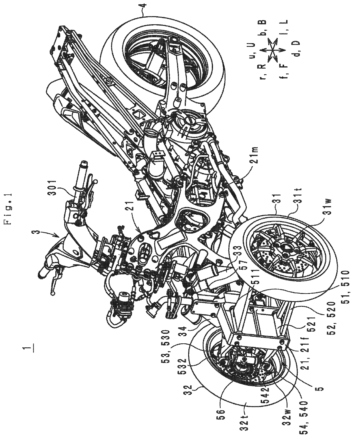
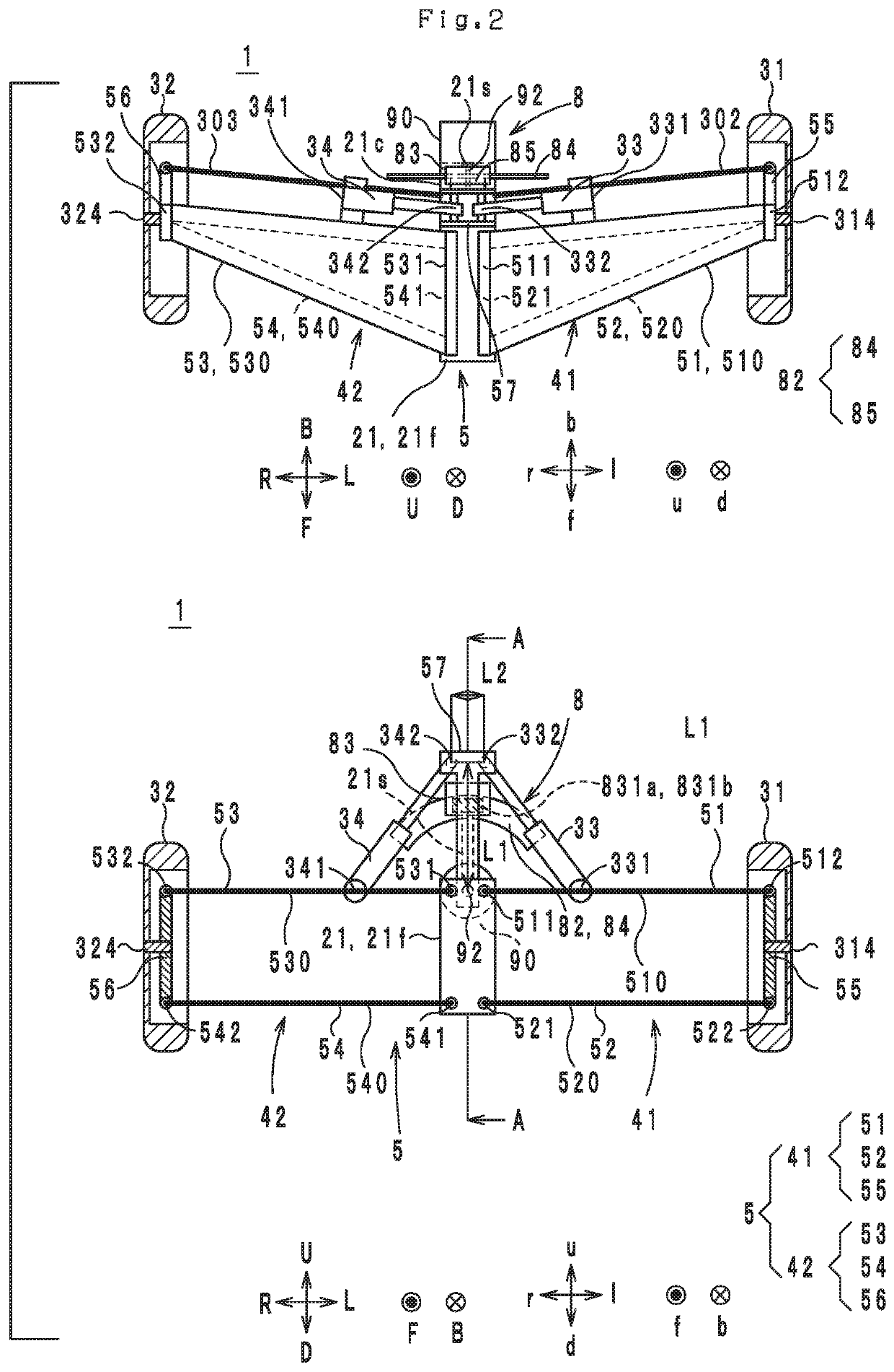
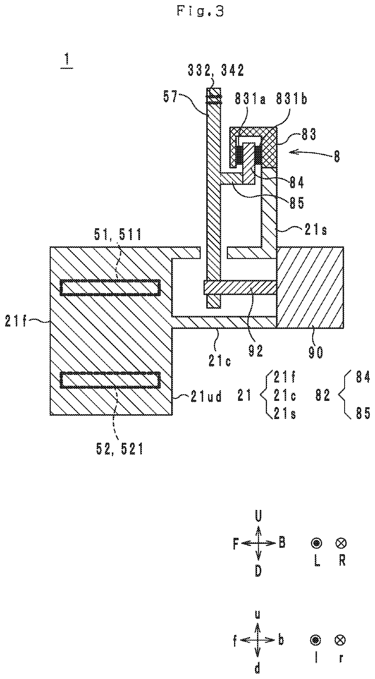
[0141]Hereunder, the overall configuration of a leaning vehicle 1 according to one embodiment of the present invention is described with reference to the accompanying drawings. In the present embodiment, a three-wheeled leaning vehicle (hereinafter, called a “leaning vehicle”) having a vehicle body frame that is capable of leaning, two front wheel tire assemblies, and one rear wheel tire assembly is described as one example of a leaning vehicle. FIG. 1 is a perspective view of the leaning vehicle 1. FIG. 2 is a multiple view drawing showing schematic diagrams of a front part of the leaning vehicle 1 as seen in a downward direction D and a backward direction B. FIG. 3 is a cross-sectional structural drawing along a line A-A in FIG. 2. FIG. 4 is a perspective view of the front part of the leaning vehicle 1. FIG. 5 is a view of the front part of the leaning vehicle 1 as seen in a frontward direction F.FIG. 6 is a view of the front part of the leaning vehicl...


PUM


Abstract

In a leaning vehicle, a shock absorber tower is disposed further forward in a vehicle-body-frame frontward direction than an upper-left-arm-member supported part at which an upper-left arm member to which a first end part of a left shock absorber is connected is supported by the vehicle body frame, and an upper-right-arm-member supported part at which an upper-right arm member to which a first end part of a right shock absorber is connected is supported by the vehicle body frame.

Description

CROSS-REFERENCE TO RELATED APPLICATIONS[0001]This application is a continuation of International Application PCT / JP2018 / 030153 filed on Aug. 10, 2018, which claims priority from Japanese Patent Application No. 2017-169542 filed on Sep. 4, 2017. The contents of each of the identified applications are entirely incorporated herein by reference.BACKGROUNDTechnical Field[0002]The present invention relates to a leaning vehicle that includes a left wheel tire assembly and a right wheel tire assembly.Background Art[0003]Leaning vehicles disclosed in, for example, Patent Literature 1 to Patent Literature 5 (identified further on) are known as conventional leaning vehicles. The leaning vehicles disclosed in Patent Literature 1 to Patent Literature 5 include a vehicle body frame, a left wheel tire assembly, a right wheel tire assembly, a left shock absorber, a right shock absorber, a link mechanism and a shock absorber tower.[0004]The link mechanism is a double wishbone-type link mechanism. Th...

Claims


Application Information

Patent Timeline
Patent Type & Authority Applications(United States)
IPC IPC(8): B62K5/10B62K5/05B60G21/00B62D9/02B62K5/027B60G21/05B60G13/00B60W30/04
CPCB62K5/10B60G21/05B60G13/003B60G21/007B60G2400/0511B62K5/027B62K5/05B60W2030/043B60G2300/122B62D9/02B60W30/04B60G3/20B62K5/08
Inventor TAKIMOTO, HIROSHI
Owner YAMAHA MOTOR CO LTD
Learn More