Seal Assembly for Reciprocating Compressor

a compressor and seal assembly technology, applied in the direction of engine seals, pump parameters, pump components, etc., can solve the problems of leakage, improper sealation of rod packing, environmental contamination hazards, etc., and achieve the effect of reducing compressive load

Active Publication Date: 2020-04-02
AIR PROD & CHEM INC
View PDF9 Cites 4 Cited by
  • Summary
  • Abstract
  • Description
  • Claims
  • Application Information

AI Technical Summary

Benefits of technology

[0020]Aspect 5. The seal assembly according to any one of aspects 1 to 4 wherein the packing (32) contained in each of the one or more packing retainers (30) is a segmented packing.
[0021]Aspect 6. The seal assembly according to any one of aspects 1 to 4 wherein the packing (32) contained in each of the one or more packing retainers (30) is a rope packing.
[0022]Aspect 7. The seal assembly according to any one of aspects 1 to 6 further comprising a bushing (80) for the reciprocating rod (20), the bushing (80) in a position effective to reduce the compressive load on the unsegmented seal (40).
[0023]Aspect 8. The seal assembly according to any one of aspects 1 to 7 further comprising a seal carrier (45) in fixed spaced relation to the one or more packing retainers (30), the seal carrier (45) for retaining the unsegmented seal (40).

Problems solved by technology

Conventionally, rod packing is designed to seal the high pressure chamber of the compressor but due to the segmented design of these sealing systems, some leakage occurs.
When the compressor or pump is non-operational, however, the piston rod is static or not moving.
The rod packing may not seal properly when the compressor, pump, or valve, in certain embodiments, is shut down but at operating pressures.
At best, the leakage results in system loss that must be replaced resulting in inefficiencies.
At worst, the leakage results in an environmental contamination hazard that is regulated by government agencies.
There are numerous problems with allowing a compressor to leak to atmosphere after shutdown.
One issue regards the potential for air ingress once gas pressure in the machine has dropped to atmospheric pressure.
With no pressure in the machine, minor leakage paths have the potential of allowing air to get inside the compressor and into the process stream, producing a potentially explosive atmosphere in the compressor or downstream of the compressor.
Water that may enter the machine during shutdown is another problem that may produce contaminants in the process flow.
Loss of product is generally small but is another problem especially if the gas leaking out is flammable, corrosive or otherwise a problem to vent to atmosphere.
The problem with having a seal of some sort that can prevent leakage to atmosphere during shutdown is one of the more difficult issues to solve.
They are made of segments to allow for a considerable amount of wear over the life of operation.
Without segments that can move relative to each other, the amount of wear the seal can withstand before “wearing out” is extremely small.
But this configuration would present the problem of stopping all leakage that would come through the packings under normal operation, and the seal would quickly wear out.

Method used


Image

  • Seal Assembly for Reciprocating Compressor
  • Seal Assembly for Reciprocating Compressor
  • Seal Assembly for Reciprocating Compressor

Examples


example

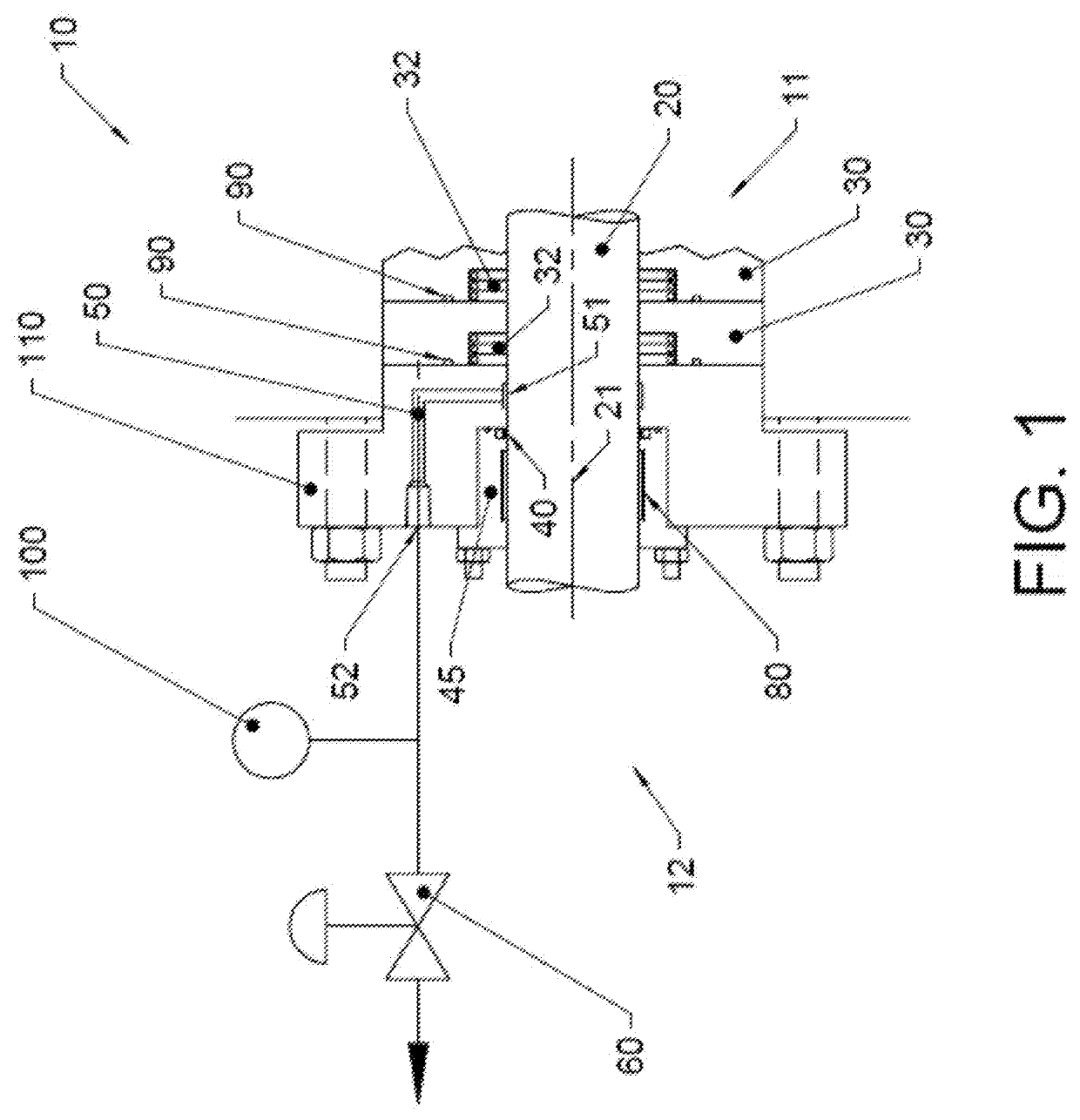
[0070]Seals wear over the course of their useful lifetime and eventually begin to leak once too much material is lost. The amount of material lost during operation is a function of both contact pressure and the total distance over which the seal has traveled. The higher the contact pressure and the greater the total sliding distance, the higher will be the total loss of material. This loss of material eventually results in the seal ‘wearing out’. The sliding distance is equal to the velocity of the sliding multiplied by the total time, so the total amount of material lost during operation per unit time is linearly related to the contact pressure (P) and the velocity (V). The higher the PV, the faster the seal will wear out.

[0071]To increase the amount of time a seal can remain in service, either the velocity can be reduced, which may not be possible for a given application, or the contact pressure can be reduced. The contact pressure is primarily a function of the pressure different...


PUM


Abstract

A seal assembly for a reciprocating rod of a reciprocating compressor, a reciprocating compressor with the seal assembly, and a method of operating the reciprocating compressor with the seal assembly to prevent leakage of gas once the compressor has been shut down. The pressure difference between opposite sides of a static seal is kept low during normal operation to reduce wear of the static seal. When the compressor is shut down, a high pressure difference between opposite sides of the static seal assists with sealing.

Description

BACKGROUND[0001]Compressors and other reciprocating pumps generally have a piston rod that moves into and out of a high (or low) pressure system. The pathway that the piston rod follows provides a natural leak path for the fluid (gas or liquid) into or out of the cylinder. Conventionally, rod packing is designed to seal the high pressure chamber of the compressor but due to the segmented design of these sealing systems, some leakage occurs.[0002]When the compressor or pump is non-operational, however, the piston rod is static or not moving. The rod packing may not seal properly when the compressor, pump, or valve, in certain embodiments, is shut down but at operating pressures. The fluid, such as for example air or natural gas, may leak past the packing rings of the rod packing to the atmosphere. At best, the leakage results in system loss that must be replaced resulting in inefficiencies. At worst, the leakage results in an environmental contamination hazard that is regulated by go...

Claims


Application Information

Patent Timeline
Patent Type & Authority Applications(United States)
IPC IPC(8): F04B39/04F16J15/38F16J15/3284F04B39/12
CPCF04B39/045F04B39/128F16J15/3284F16J15/38F16J15/56F16J15/40F04B39/041F04B39/0022F04B49/22F04B49/10F04B2201/0208F16J15/004F16J15/3296F05B2240/57
Inventor CHALK, DAVID JONATHAN
Owner AIR PROD & CHEM INC
Why Eureka
Try Eureka