
Cross-term spatiotemporal encoding for magnetic resonance imaging

a magnetic resonance imaging and spatiotemporal encoder technology, applied in the field of magnetic resonance imaging, can solve problems such as nullifying the resulting detectable signal

Active Publication Date: 2020-04-09
YEDA RES & DEV CO LTD
View PDF6 Cites 3 Cited by
  • Summary
  • Abstract
  • Description
  • Claims
  • Application Information

AI Technical Summary

Benefits of technology

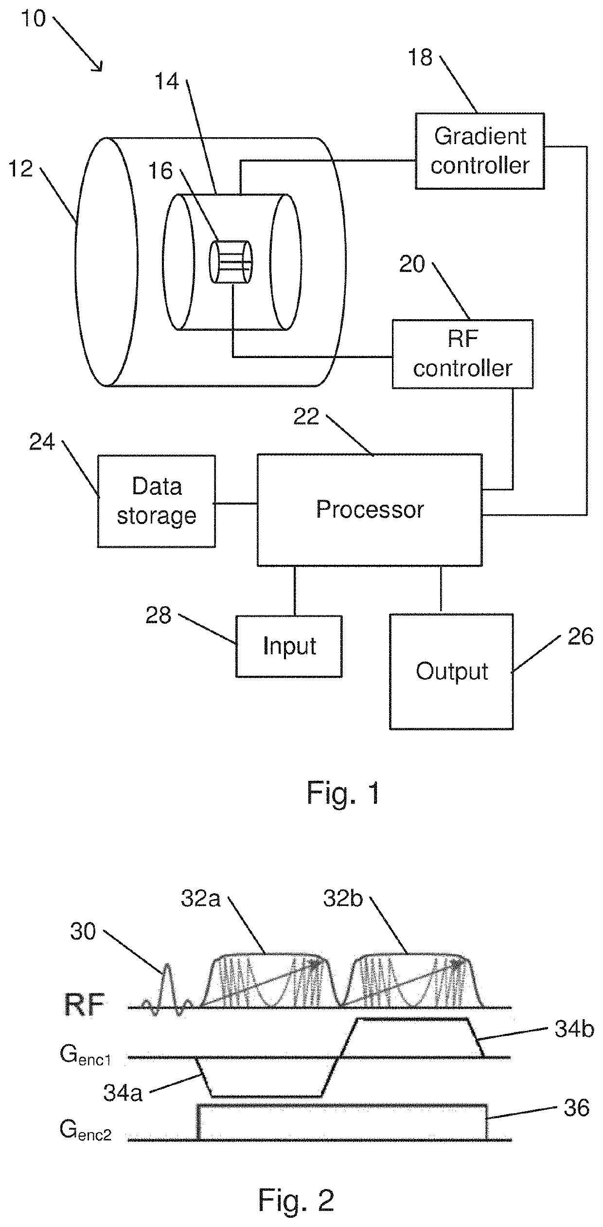
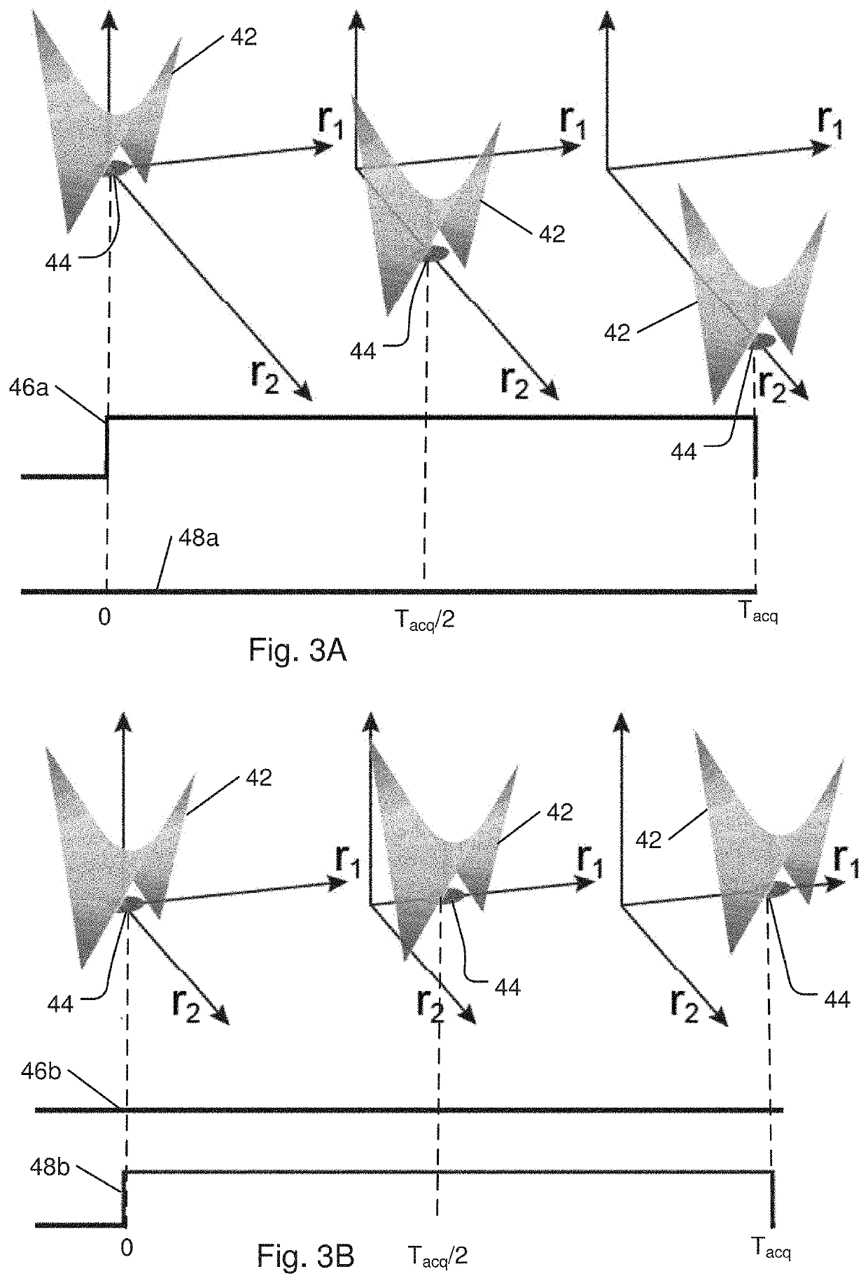
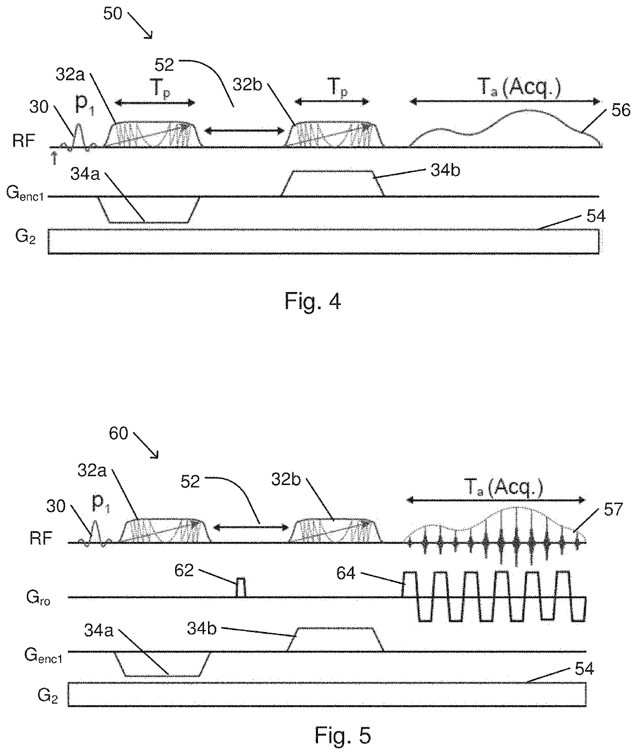
The present invention provides a method for MRI imaging of a subject using a special encoding scheme that allows for the simultaneous measurement of spins in two directions. This encoding scheme involves applying two chirped RF pulses and two magnetic field gradient pulses, with opposite polarities, to spatially encode the spins. The method also includes measuring the spin signal while applying a constant readout magnetic field gradient. The length of the delay between the first and second RF pulses can be adjusted to cover a selected field of view. The technical effects of this method include improved image quality and reduced image acquisition time.

Problems solved by technology

For all other positions, the rapidly varying phase leads to destructive interference among neighboring contributions, thus nullifying the resulting detectable signal.

Method used


Image

  • Cross-term spatiotemporal encoding for magnetic resonance imaging
  • Cross-term spatiotemporal encoding for magnetic resonance imaging
  • Cross-term spatiotemporal encoding for magnetic resonance imaging

Examples


Embodiment Construction

[0056]In the following detailed description, numerous specific details are set forth in order to provide a thorough understanding of the invention. However, it will be understood by those of ordinary skill in the art that the invention may be practiced without these specific details. In other instances, well-known methods, procedures, components, modules, units and / or circuits have not been described in detail so as not to obscure the invention,

[0057]Although embodiments of the invention are not limited in this regard, discussions utilizing terms such as, for example, “processing,”“computing,”“calculating,”“determining,”“establishing”, “analyzing”, “checking”, or the like, may refer to operation(s) and / or process(es) of a computer, a computing platform, a computing system, or other electronic computing device, that manipulates and / or transforms data represented as physical (e.g., electronic) quantities within the computer's registers and / or memories into other data similarly represe...


PUM


Abstract

A method for MRI imaging of a subject includes spatially encoding spins in a slice of the subject in orthogonal first and second directions. The encoding includes applying a chirped radiofrequency (RF) pulse concurrently with application of a magnetic field gradient pulse along the first direction. After applying of the RF pulse, a second chirped RF pulse is applied concurrently with application of a second magnetic field gradient pulse, with polarity opposite that of the first gradient pulse. An encoding magnetic field gradient, constant from applying the first RF pulse until the end of applying the second RF pulse, is concurrently applied along the second direction. Following the encoding, a spin signal is measured concurrently with application of a constant readout magnetic field gradient.

Description

CROSS REFERENCE TO RELATED APPLICATIONS[0001]The present invention is a continuation in part of International Application No. PCT / IL2016 / 050850, filed on Aug. 4, 2016 and published as International Publication Number WO 2017 / 021967 on Feb. 9, 2017, and which claims the priority benefit of U.S. provisional patent application No. 62 / 200,667 filed on Aug. 4, 2015, all of which are incorporated in their entirety herein by reference.FIELD OF THE INVENTION[0002]The present invention relates to magnetic resonance imaging.BACKGROUND OF THE INVENTION[0003]Nuclear magnetic resonance (NMR) finds its widest contemporary application within the context of magnetic resonance imaging (MRI). MRI measurements and experiments traditionally retrieve the multidimensional spin density p(r). The multidimensional spin density is measured by acquisition of a free induction decay (FID) signal that is collected under the action of linear field gradients G=(Gx, Gy, Gz) acting along orthogonal axes. Gradients d...

Claims


Application Information

Patent Timeline
IPC IPC(8): G01R33/561G01R33/54
CPCG01R33/5616G01R33/543G01R33/4806G01R33/561G01R33/56341G01R33/56509G01R33/56527G01R33/56536G01R33/56563
Inventor FRYDMAN, LUCIOZHANG, ZHIYONGLUSTIG, SHIMON MICHAEL
Owner YEDA RES & DEV CO LTD
Learn More