

Quantized depths for projection point cloud compression
a projection point cloud and compression technology, applied in the field of compression and decompression of point clouds, can solve the problems of cost and time-consuming storage and transmission
- Summary
- Abstract
- Description
- Claims
- Application Information
AI Technical Summary
Benefits of technology
Problems solved by technology
Method used
Image

Examples
example intra — 3d
Example Intra—3D Frame Encoder
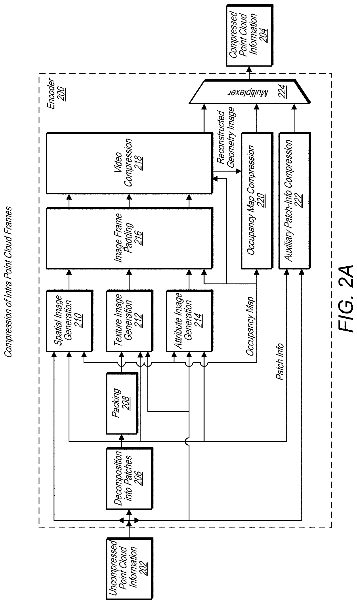
[0086]FIG. 2A illustrates components of an encoder for encoding intra point cloud frames, according to some embodiments. In some embodiments, the encoder described above in regard to FIG. 1 may operate in a similar manner as encoder 200 described in FIG. 2A and encoder 250 described in FIG. 2C.
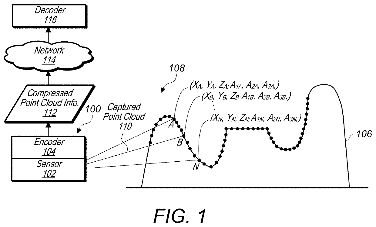
[0087]The encoder 200 receives uncompressed point cloud 202 and generates compressed point cloud information 204. In some embodiments, an encoder, such as encoder 200, may receive the uncompressed point cloud 202 from a sensor, such as sensor 102 illustrated in FIG. 1, or, in some embodiments, may receive the uncompressed point cloud 202 from another source, such as a graphics generation component that generates the uncompressed point cloud in software, as an example.
[0088]In some embodiments, an encoder, such as encoder 200, includes decomposition into patches module 206, packing module 208, spatial image generation module 210, texture image generation module 212...
example intra 3d
Frame Decoder
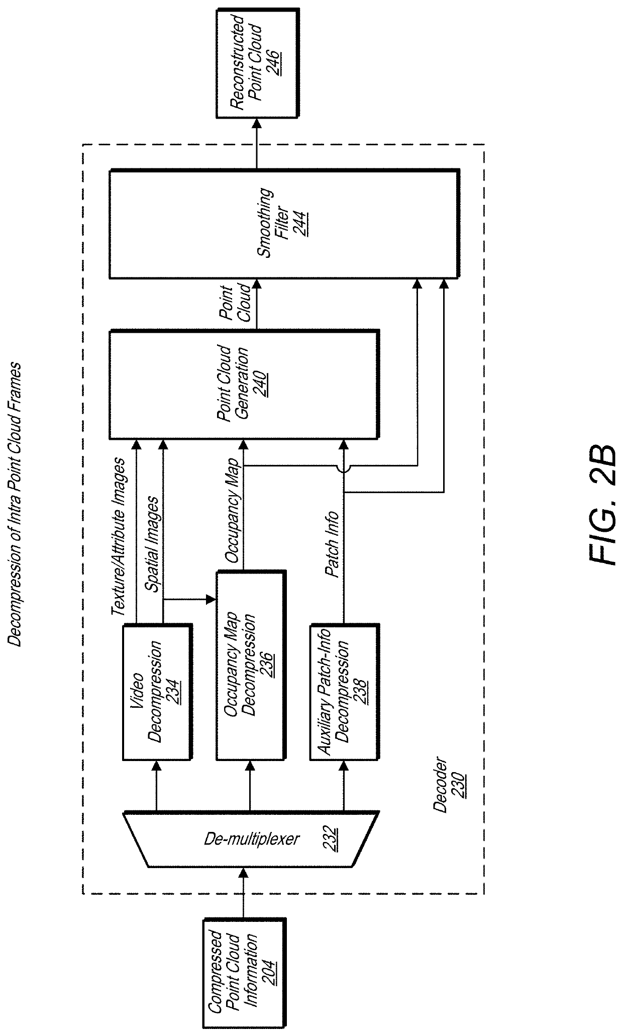
[0095]FIG. 2B illustrates components of a decoder for decoding intra point cloud frames, according to some embodiments. Decoder 230 receives compressed point cloud information 204, which may be the same compressed point cloud information 204 generated by encoder 200. Decoder 230 generates reconstructed point cloud 246 based on receiving the compressed point cloud information 204.
[0096]In some embodiments, a decoder, such as decoder 230, includes a de-multiplexer 232, a video decompression module 234, an occupancy map decompression module 236, and an auxiliary patch-information decompression module 238. Additionally a decoder, such as decoder 230 includes a point cloud generation module 240, which reconstructs a point cloud based on patch images included in one or more image frames included in the received compressed point cloud information, such as compressed point cloud information 204. In some embodiments, a decoder, such as decoder 203, further comprises a smoothing ...
example closed form
Solution
[0374]For each point Prec(i) in the reconstructed point cloud, let Q*(i) be its nearest neighbor in the original point cloud. For each point Prec(i) in the reconstructed point cloud, let (Q+(i, h))h∈{1, . . . , H(i)} be the set of point in the original point cloud that share Prec(i) as their nearest neighbor in the reconstructed point cloud. Let +(i) be the centroid of (Q+(i, h))h∈{1, . . . , H(i)}.
If H=0, then C(Prec(i))=C(Q*(i))
[0375]Denote as R-G-B vector C(P) associated with a given point P. In order to compute the color for a given Prec(i), we have the following formulation:
argminC(Prec(i))max{1NrecC(Prec(i))-C(Q*(i))2,1N∑h=1HC(Prec(i))-C(Q+(i,h))2}Wheremax{1NrecC(Prec(i))-C(Q*(i))2,∑h=1HC(Prec(i))-C(ℚ+(i))+C(ℚ+(i))-C(Q+(i,h))2}=max{1NrecC(Prec(i))-C(Q*(i))2,HNC(Prec(i))-C(ℚ+(i))2+1N∑h=1HC(ℚ+(i))-C(Q+(i,h))2+2N∑h=1H〈C(Prec(i))-C(ℚ+(i)),C(ℚ+(i))-C(Q+(i,h))〉}=max{1NrecC(Prec(i))-C(Q*(i)2,HNC(Prec(i))-C(ℚ+(i))2+1N∑h=1HC(ℚ+(i))-C(Q+(i,h))2}
[0376]Now denote D2=Σh=1H∥C(+(i))−...
PUM
 Abstract
Description
Claims
Application Information