Eureka AIR delivers breakthrough ideas for toughest innovation challenges, trusted by R&D personnel around the world.

Diaphragm, speaker unit using same, headphones, and earphones

a technology of diaphragm and speaker unit, which is applied in the direction of transducer diaphragm, electrical transducer, earpiece/earphone attachment, etc., can solve the problems of increasing the likelihood of diaphragm rolling or abnormal noise, and affecting the reproduction sound quality, etc., to suppress diaphragm rolling and distortion, suppress the effect of even-order distortion and improving the symmetry of the edge portion of the diaphra

Active Publication Date: 2020-04-09
ONKYO KK
View PDF0 Cites 2 Cited by
  • Summary
  • Abstract
  • Description
  • Claims
  • Application Information

AI Technical Summary

Benefits of technology

This patent describes a new design for a diaphragm used in headphone and speaker technology. The design includes inclined ribs in addition to conventional tangential ribs, which improves the displacement symmetry of the diaphragm and reduces the likelihood of issues like rolling or abnormal noise. The inclined ribs also contribute to improved high-frequency sound quality. Overall, this design creates a more symmetrical and high-quality sound reproduction.

Problems solved by technology

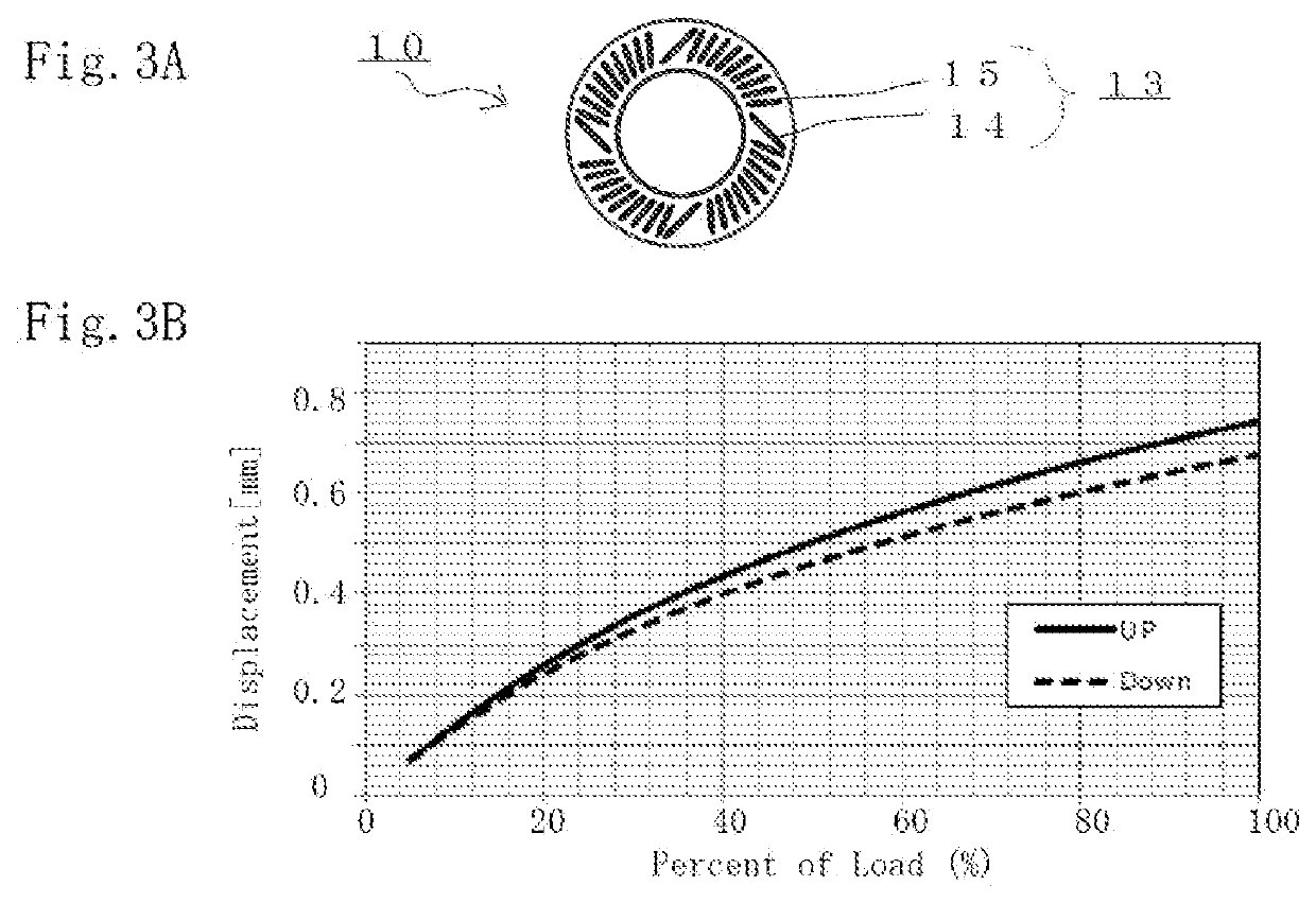
As discussed in JP-UM-A-62-139191, when the diaphragm vibrates vertically, if the ease of motion of the edge portion varies between the up direction and the down direction, that is, if the displacement symmetry of the edge portion varies and the linearity of the diaphragm deteriorates, troubles such as diaphragm rolling or the occurrence of abnormal noise become more likely to occur.
If the displacement symmetry of the edge portion varies, the likelihood of an increase in the even-order distortion of sound waves emitted from the electrodynamic speaker unit increases, resulting in degradation of the reproduced sound quality.

Method used


Image

  • Diaphragm, speaker unit using same, headphones, and earphones
  • Diaphragm, speaker unit using same, headphones, and earphones
  • Diaphragm, speaker unit using same, headphones, and earphones

Examples


first embodiment

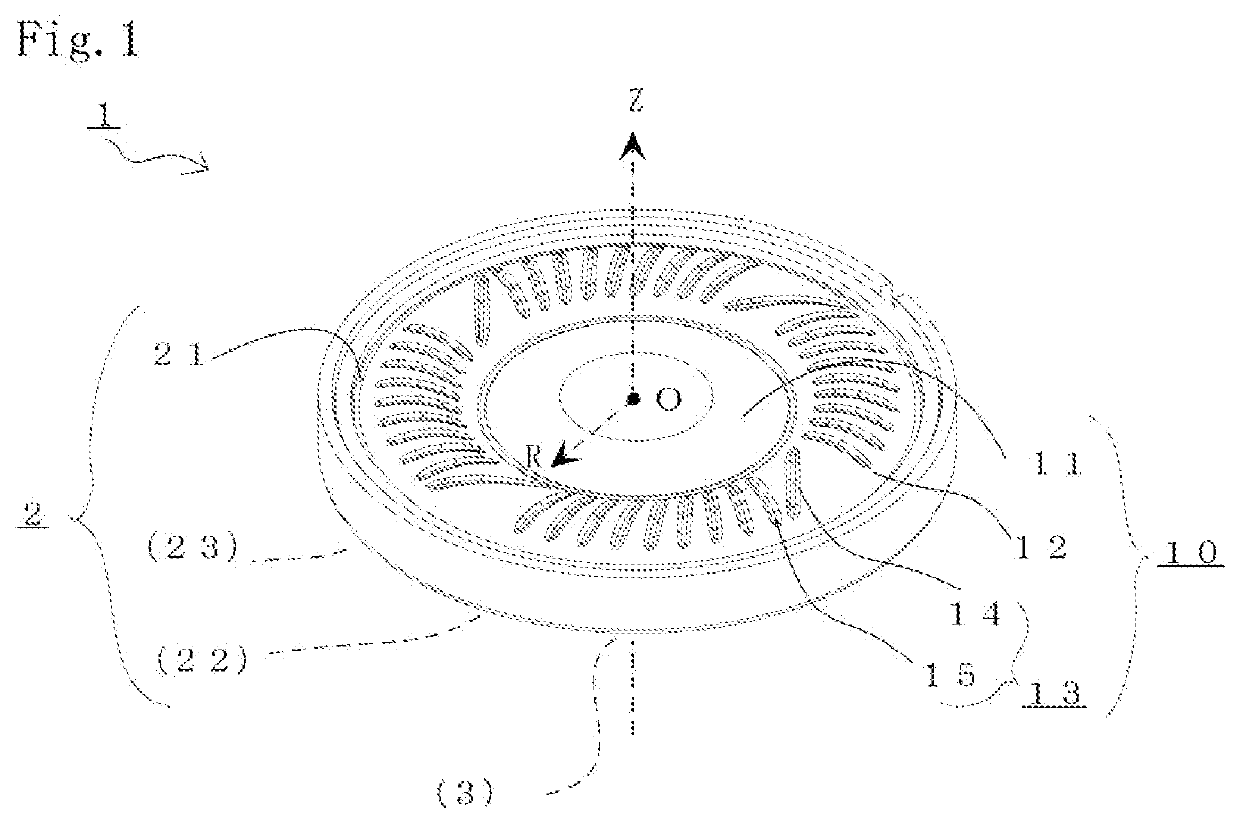
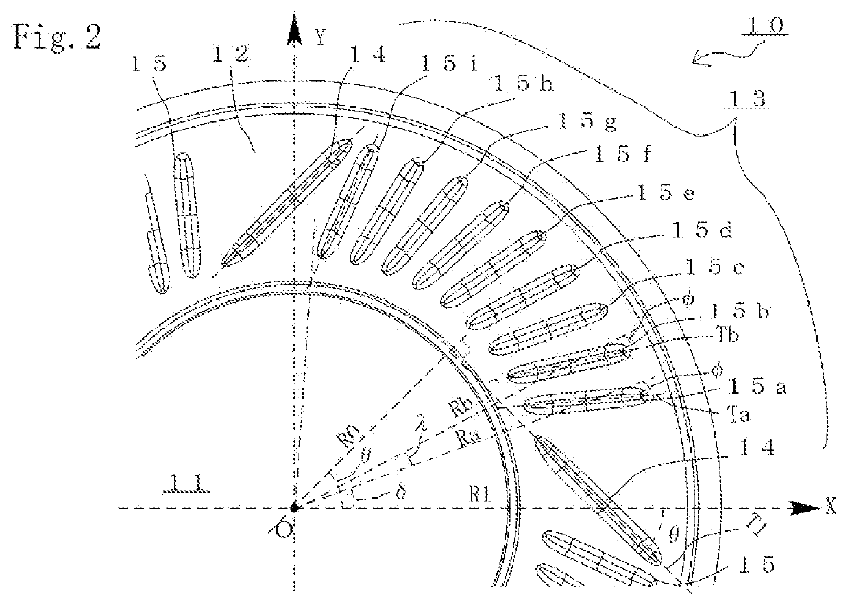
[0033]FIG. 1 is a diagram for describing an electrodynamic speaker unit 1 used in headphones and earphones according to a preferred embodiment of the present invention. Specifically, FIG. 1 is a perspective view from the front side, illustrating the appearance of the speaker unit 1. FIG. 2 is a partially enlarged plan view for describing the shape of the diaphragm 10 of the speaker unit 1. The form of the speaker unit 1 is not limited to the case of the present embodiment. Diagrammatic depiction and description of the configuration of the speaker unit 1 that is not required for describing the present invention are omitted.

[0034]The speaker unit 1 of the present embodiment is an electrodynamic speaker with a nominal diameter of 40 mm which is used in headphones disposed in proximity to a user's ears. The speaker unit 1 of the present embodiment is suitable for headphones when the nominal diameter is 35 to 50 mm, for example. When the nominal diameter is smaller, such as 5 to 10 mm, t...


PUM


Abstract

Displacement symmetry of a diaphragm is improved to prevent the occurrence of troubles such as diaphragm rolling or the occurrence of abnormal noise, thereby providing high reproduced sound quality. The diaphragm includes an annular edge portion having a convex radial cross section formed by molding a sheet-like member or a film-like member. The edge portion has a plurality of rotationally symmetrical recessed ribs formed by recessing a convex surface. The plurality of recessed ribs includes at least a first rib disposed along a first prescribed line intersecting, at an angle of 45°, a first radial line passing a center point, and a second rib arranged in a position not intersecting but adjacent to the first rib and disposed along a second prescribed line intersecting the second radial line at a predetermined angle of less than 45°.

Description

BACKGROUND OF THE INVENTION1. Field of the Invention[0001]The present invention relates to a diaphragm of an electrodynamic speaker unit used in headphones and earphones which are worn on a user's ears for audio reproduction.2. Description of the Related Art[0002]In a small-sized electrodynamic speaker unit for use in headphones and earphones, a diaphragm may be used in which a dome portion and an edge portion extending from the outer periphery of the dome portion are integrally configured by molding a film-like member made of a resin material, such as polyethylene terephthalate (PET) or polyetherimide (PEI). In the electrodynamic speaker, a voice coil to which an audio signal current is supplied from the back side is mounted to a connected portion of the dome portion at the center of the diaphragm and the edge portion, which are integrally configured. The outer peripheral end side of the edge portion of the diaphragm is fixed to a frame linked with a small and lightweight magnetic ...

Claims


Application Information

Patent Timeline
Patent Type & Authority Applications(United States)
IPC IPC(8): H04R9/06H04R1/10H04R7/12H04R7/18H04R9/02H04R31/00
CPCH04R31/003H04R9/025H04R7/127H04R9/06H04R7/18H04R1/10H04R2400/11
Inventor FUJITANI, TAKESHI
Owner ONKYO KK
Why Eureka
Eureka Blog
Learn More