Eureka AIR delivers breakthrough ideas for toughest innovation challenges, trusted by R&D personnel around the world.

Wearable device antenna system

Pending Publication Date: 2020-04-16
SNAP INC
View PDF21 Cites 6 Cited by
  • Summary
  • Abstract
  • Description
  • Claims
  • Application Information

AI Technical Summary

Benefits of technology

The patent text discusses the challenge of miniaturizing wireless communication systems in electronic devices while maintaining their functionality. This is particularly difficult in wearable devices where battery power is often at a premium. The text describes various antenna systems and their limitations in achieving miniaturization, and proposes new solutions. The technical effects of the patent text include providing antenna systems that can be smaller while still achieving reliable wireless connectivity, and improving heat management in wearable electronic devices.

Problems solved by technology

A bottleneck in achieving further progress is the relatively slower pace of antenna system miniaturization.
The result was antenna miniaturization with minimal performance impact.
As a result, these systems thus far had to be content with narrow bandwidth, poor efficiency and slower speeds.
Thus, existing antenna systems for many electronic devices are incapable of providing sufficiently efficient wireless data transfer for functionalities such as uploading high-definition video captured by the eyewear device to other devices, particularly limitations of battery-powered operation are considered.

Method used


Image

  • Wearable device antenna system
  • Wearable device antenna system
  • Wearable device antenna system

Examples


example 1

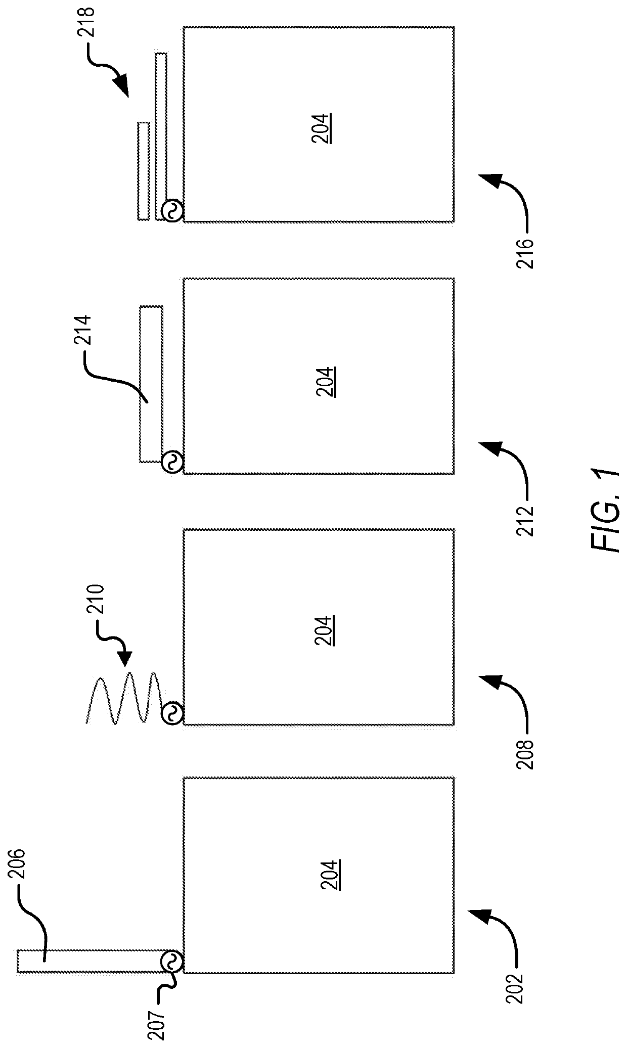
[0091]An antenna system comprising:[0092]a driven antenna element;[0093]a printed circuit board (PCB) that carries on-board electronics communicatively coupled to the driven antenna element to communicate wireless signals via the driven antenna element, the PCB defining a PCB ground plane for co-operation with the driven antenna element in signal communication; and[0094]a PCB extender comprising a conductor electrically connected to the PCB ground plane and projecting from the PCB for co-operation with the driven antenna element in signal communication.

example 2

[0095]The antenna system of example 1, which comprises a plurality of PCB extenders electrically connected to the PCB ground plane and projecting from the PCB in mutually transverse orientations, thereby defining a plurality of mutually transverse ground planes for the driven antenna element. At least one of the plurality of PCB extenders may form a structural component of a device in which the antenna system is incorporated.

example 3

[0096]The antenna system of example 2, wherein the plurality of PCB extenders comprises a pair of PCB extenders that are substantially orthogonal relative to one another.


PUM


Abstract

An antenna system comprises a driven antenna element connected to a printed circuit board (PCB), and a plurality of PCB extenders provided by electrical conductors connected to a PCB ground plane for cooperation with the driven antenna element in signal communication. In an eyewear device that incorporates the antenna system, the plurality of PCB extenders are provided by conductive structural elements incorporated in an eyewear frame.

Description

PRIORITY APPLICATION[0001]This application claims priority to U.S. Provisional Application Ser. No. 62 / 467,675, filed Mar. 6, 2017, the disclosure of which is incorporated herein in its entirety by reference.TECHNICAL FIELD[0002]This disclosure relates generally to wireless communication. Aspects of the disclosure relate to wireless communication systems, antenna systems forming part of such wireless communication systems, and electronic devices with wireless communication functionality. The disclosure further relates to electronics-enabled eyewear devices.BACKGROUND[0003]Recent trends in consumer electronics have consistently been towards greater miniaturization, while the functionalities of such devices demand increasingly ubiquitous wireless connectivity. Wireless communication systems forming part of electronic devices with a limited form factor struggle to meet the conflicting requirements for increasing compactness while achieving wireless connectivity capable of reliably tran...

Claims


Application Information

Patent Timeline
IPC IPC(8): H01Q1/27H01Q1/48H05K1/02H01Q9/04H05K1/14G02C11/00
CPCH01Q9/0407H05K2201/10098H01Q1/273H05K1/14H05K1/0203G02C11/10H05K1/0237H01Q1/48H01Q9/30H01Q5/357H01Q1/02H05K7/2039G02C5/22H01Q1/38
Inventor ASHWOOD, ANDREAKUSBEL, PATRICKLIN, JUNMOSKOWITZ, DOUGLAS WAYNEOLGUN, UGURPATTON, RUSSELL DOUGLASSIMONS, PATRICK TIMOTHY MCSWEENESTEGER, STEPHEN ANDREW
Owner SNAP INC
Why Eureka
Eureka Blog
Learn More