Efficient electric power conversion

Active Publication Date: 2020-04-16
BERNER FACHHOCHSCHULE
View PDF0 Cites 2 Cited by
  • Summary
  • Abstract
  • Description
  • Claims
  • Application Information

AI Technical Summary

Benefits of technology

The power transmission unit described in this patent allows for efficient and reliable power transfer between two AC power units without the need for a phase shift between their voltages. This results in a high power factor and minimum reactive power during the transfer. The main transformer and auxiliary AC unit can operate at high efficiency, even at high switching frequencies. The auxiliary AC unit provides only the necessary voltage to control the power flow, minimizing losses and improving the overall efficiency of the transmission unit. This makes the power transmission unit suitable for high switching frequencies and allows for higher power density and reduced size and weight of the main transformer.

Problems solved by technology

A first disadvantage of this approach is that the phase shift necessary to establish a power flow generates a significant flow of reactive power which causes significant losses in the converters.
Another disadvantage is that the power switches of the converters are switched at peak power, i.e. peak voltage and / or peak current which generates significant switching losses.
Otherwise, natural commutation of the bridge devices will occur resulting in switching losses.
Another disadvantage is that the phase shift between the voltages, and therefore also between the voltages and the current, has to be increased in order to increase the transmitted power of the converter.
This results however in a lower power factor and increased losses due to the increased reactive current component.
However, the amplitude and the shape of the current can not be controlled.
This results in high conduction losses especially at small power flows as compared to rated power flow.
In other words, the useful and efficient operational range of resonant converters is limited.
Such inductors however can be bulky, heavy and expensive.
Further, the disclosed DC-DC converter is not suitable for bidirectional operation.

Method used


Image

  • Efficient electric power conversion
  • Efficient electric power conversion
  • Efficient electric power conversion

Examples


first embodiment

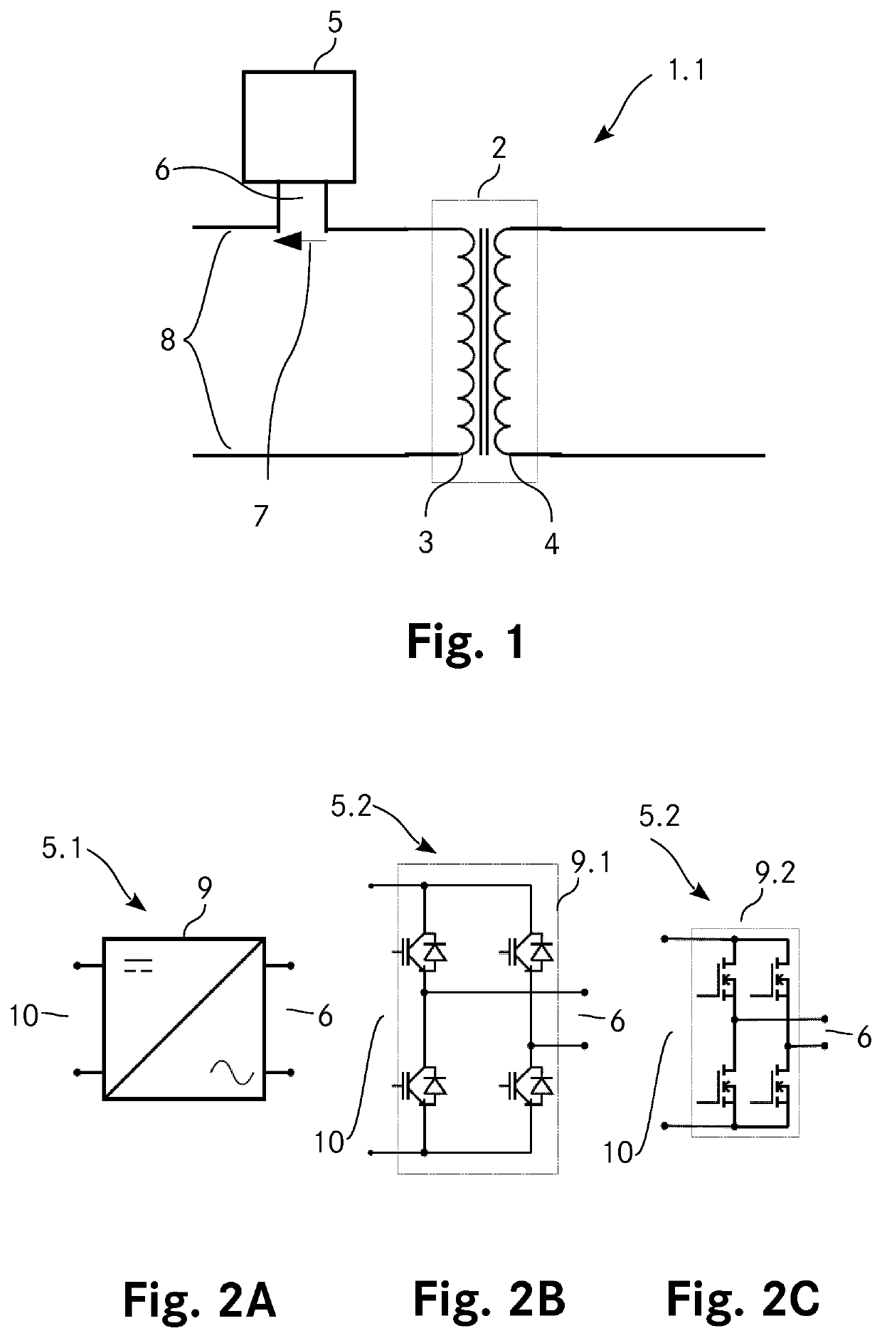
[0138]FIG. 1 shows a power transmission unit 1.1 according to the invention. The power transmission unit 1.1 comprises a main transformer 2 having a first winding 3 and a second winding 4. The power transmission unit 1.1 further comprises a switchable auxiliary AC unit 5 with an auxiliary AC side 6. The auxiliary AC unit 5 provides a tunable auxiliary AC voltage 7 across the auxiliary AC side 6. The auxiliary AC side 6 of the auxiliary AC unit 5 is connected in series with the first winding 3 of the main transformer 2 to form a series connection 8. The series connection 8 of the power transmission unit 1 can be connected to an AC power unit (not shown). For proper operation of the power transmission unit 1.1, the series connection 8 should not be shorted.

[0139]FIG. 2A shows a first possible embodiment of the switchable auxiliary AC unit 5.1. In the present case, the auxiliary AC unit 5.1 comprises a converter 9 which is a DC AC converter. The auxiliary AC unit 5.1 has in addition to...

second embodiment

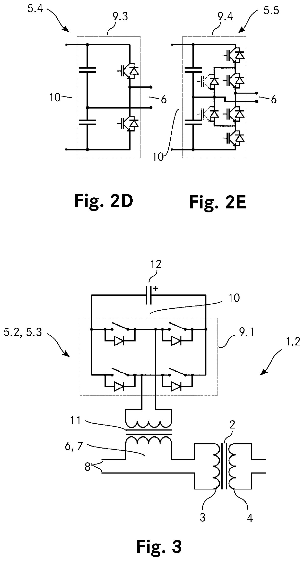
[0148]Although shown together in this second embodiment of the power transmission unit 1.2, the auxiliary AC unit 5.2, 5.3 is not required to comprise the auxiliary transformer 11 and the energy storage 12. Thus, the auxiliary transformer 11 connecting the AC side of the full bridge converter 9.1, 9.2 in series with the first winding 3 of the main transformer 2 can be omitted. Similarly, the energy storage 12 and / or the full bridge converter 9.1 can be omitted.

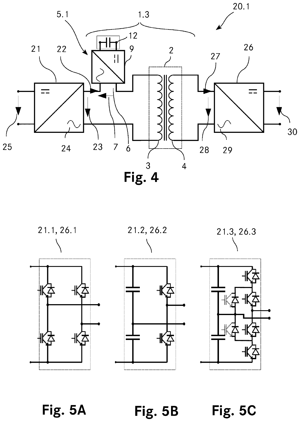
[0149]FIG. 4 shows a first possible embodiment of a power conversion unit 20.1 comprising a power transmission unit 1.3 according to the invention. The power conversion unit 20.1 comprises a first AC power unit 21 providing a first current 22 and a first AC voltage 23 across a first AC side 24 of the first AC power unit 21. The first AC power unit 21 is a DC AC converter fed by a first main voltage 25 which is in this embodiment of the power conversion unit 20.1 a DC voltage. The first AC side 24 of the first AC power unit 21 ...

fourth embodiment

[0168]FIG. 10 shows a fifth possible embodiment of a power conversion unit 20.5 which comprises a first AC power unit 21.4 with a three phase converter and the second AC power unit 26.4 with another three phase converter. The main transformer 2 of this power conversion unit 20.5 is as well configured as three phase transformer with a first winding 3 having three phases and a second winding 4 having three phases. The three AC phases of the converter of the first AC power unit 21.4 are each connected in series to a different full bridge converter 5.2, 5.3 which is further connected to a respective phase of the first winding 3 of the main transformer 2. The second AC power unit 26.4 is connected to the second winding 4 of the main transformer 2.

[0169]FIG. 11 shows a sixth possible embodiment of a power conversion unit 20.6. This embodiment is in most parts identical to the power conversion unit 20.1 shown in FIG. 4 but comprises an additional control unit 33. This control unit 33 contr...


PUM


Abstract

A power transmission unit for controlling a flow of electric energy between two AC power units is provided. The power transmission unit comprises a main transformer having a first winding and a second winding as well as a switchable auxiliary AC unit for applying a tunable auxiliary AC voltage across an auxiliary AC side of the auxiliary AC unit. The auxiliary AC side is connected in series with the first winding of the main transformer to form a series connection. Further, a power conversion unit comprising the power transmission unit and two AC power units as well as a method for controlling a flow of electric energy by using such a power conversion unit are provided.

Description

TECHNICAL FIELD[0001]The invention relates to a power transmission unit for controlling a flow of electric energy between two AC power units. The invention also relates to a power conversion unit for converting electric power. The power conversion unit comprises a power transmission unit according to the invention, a first AC power unit and a second AC power unit. Further, the invention relates to a method for controlling a flow of electric energy by using a power conversion unit according to the invention.BACKGROUND ART[0002]Electric power converters with galvanic isolation are well known. Such power converters are typically realized by using two AC-DC converters connected via a transformer. The transformer provides the galvanic isolation and the voltage level conversion. For operating such electric power converters, both AC-DC converters are operated at the same frequency. The power flow is controlled by adjusting the phase and the duty cycle of the voltage waveforms. A first disa...

Claims


Application Information

Patent Timeline
IPC IPC(8): H02M3/335H02M1/08
CPCH02M2001/0058H02M1/083H02M3/33584H02M1/0093H02M7/4835H02M1/0095Y02B70/10H02M1/0077H02J1/102H02M1/0058
Inventor MARIÉTHOZ, JEAN-SÉBASTIENDELAFORGE, TIMOTHÉ
Owner BERNER FACHHOCHSCHULE
Why Eureka
Try Eureka