Wiper motor
a technology of a wand motor and a yoke, which is applied in the direction of vehicle maintenance, vehicle cleaning, transportation and packaging, etc., can solve the problems of generating noise components, affecting the performance of the wand motor, so as to reduce the distance over which a noise component flows through the housing and suppress the noise component
- Summary
- Abstract
- Description
- Claims
- Application Information
AI Technical Summary
Benefits of technology
Problems solved by technology
Method used
Image

Examples
first exemplary embodiment
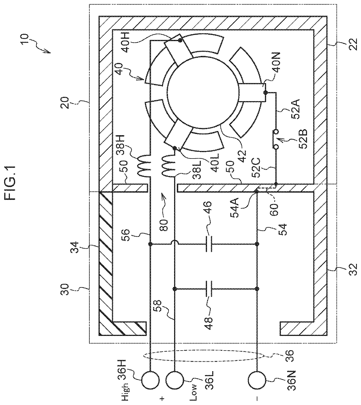
[0063]FIG. 1 is a block diagram illustrating an example of an electrical configuration of a wiper motor 10 according to the present exemplary embodiment.
[0064]As illustrated in FIG. 1, the wiper motor 10 is configured by a motor section 20 in which a stator and a rotor are housed, and a speed reduction section 30 configured by a worm gear mechanism provided at a terminal end of a rotation shaft of the rotor so as to reduce the rotation speed of the rotation shaft.
[0065]The stator and the rotor of the motor section 120 are provided within a yoke 22 configured of die-cast aluminum or the like. The interior of the yoke 22 has a hollow substantially circular cylinder shape, and the stator and the rotor are accommodated in this interior space.
[0066]The worm gear mechanism of the speed reduction section 30 mentioned above is accommodated within a die-cast aluminum housing 32. The housing 32 and the worm gear mechanism are covered by a resin housing cover 34.
[0067]A connector 36 includes a...
second exemplary embodiment
[0083]Explanation follows regarding a second exemplary embodiment of the present disclosure. As illustrated in FIG. 5, a wiper motor 12 according to the present exemplary embodiment differs from the first exemplary embodiment in the point that a third connection terminal 70 is provided. In other respects, configuration is similar to that of the first exemplary embodiment, and so detailed explanation of other configurations will be omitted.
[0084]As illustrated in FIG. 5, one end of the third connection terminal 70 is electrically connected to the ground line 54 between the other end of the capacitor 48 and the ground terminal 36N of the connector 36, and the other end of the third connection terminal 70 is electrically connected to an inner wall of the housing 32. As a result, a noise component flows from the negative terminal 40N of the brush 40 to the third connection terminal 70 through a pathway through the partitioning wall 50 and the housing 32, as illustrated by a broken line ...
third exemplary embodiment
[0089]Explanation follows regarding a third exemplary embodiment of the present disclosure. In the present exemplary embodiment, configurations equivalent to those of the first exemplary embodiment or the second exemplary embodiment are allocated the same reference numerals, and detailed explanation thereof is omitted.
[0090]As illustrated in FIG. 10, in a wiper motor according to the present exemplary embodiment, a ground line 254, a high voltage line 256, and a low voltage line 258 are installed inside a resin housing cover 234 (on the side in which a speed reduction mechanism of the wiper motor is accommodated).
[0091]One end 256H1 of the high voltage line 256 is connected to the High terminal 36H (see FIG. 2) of the connector 36, and one end 258L1 of the low voltage line 258 is connected to the Low terminal 36L (see FIG. 2) of the connector 36. One end 254N1 of the ground line 254 is connected to the ground terminal 36N of the connector 36, and extends as far as a fixing bolt conn...
PUM
 Abstract
Description
Claims
Application Information
 - R&D Engineer
- R&D Manager
- IP Professional
- Industry Leading Data Capabilities
- Powerful AI technology
- Patent DNA Extraction
Browse by: Latest US Patents, China's latest patents, Technical Efficacy Thesaurus, Application Domain, Technology Topic.
© 2024 PatSnap. All rights reserved.Legal|Privacy policy|Modern Slavery Act Transparency Statement|Sitemap