Image processing apparatus and a control method for controlling the image processing apparatus

a control method and image processing technology, applied in the field of image processing methods, can solve the problems of reducing the accuracy of ghost detection, and achieve the effect of suppressing the noise component included and reducing the undesirable component more accurately

Inactive Publication Date: 2018-01-25
CANON KK
View PDF1 Cites 0 Cited by
  • Summary
  • Abstract
  • Description
  • Claims
  • Application Information

AI Technical Summary

Benefits of technology

[0004]What is needed is an improvement to provide an image processing apparatus capable of suppressing the noise component included in a captured image and reducing the undesirable component more accurately, and a control method for controlling the image processing apparatus.

Problems solved by technology

When an image capture apparatus such as a camera captures an image, a part of the light entering the optical system is sometimes reflected on the boundary face of a lens or on a member holding the lens and reaches the image pickup plane as an undesirable light.
When each viewpoint image has a large amount of noise, the accuracy of the detection of a ghost is decreased.

Method used


Image

  • Image processing apparatus and a control method for controlling the image processing apparatus
  • Image processing apparatus and a control method for controlling the image processing apparatus
  • Image processing apparatus and a control method for controlling the image processing apparatus

Examples


first exemplary embodiment

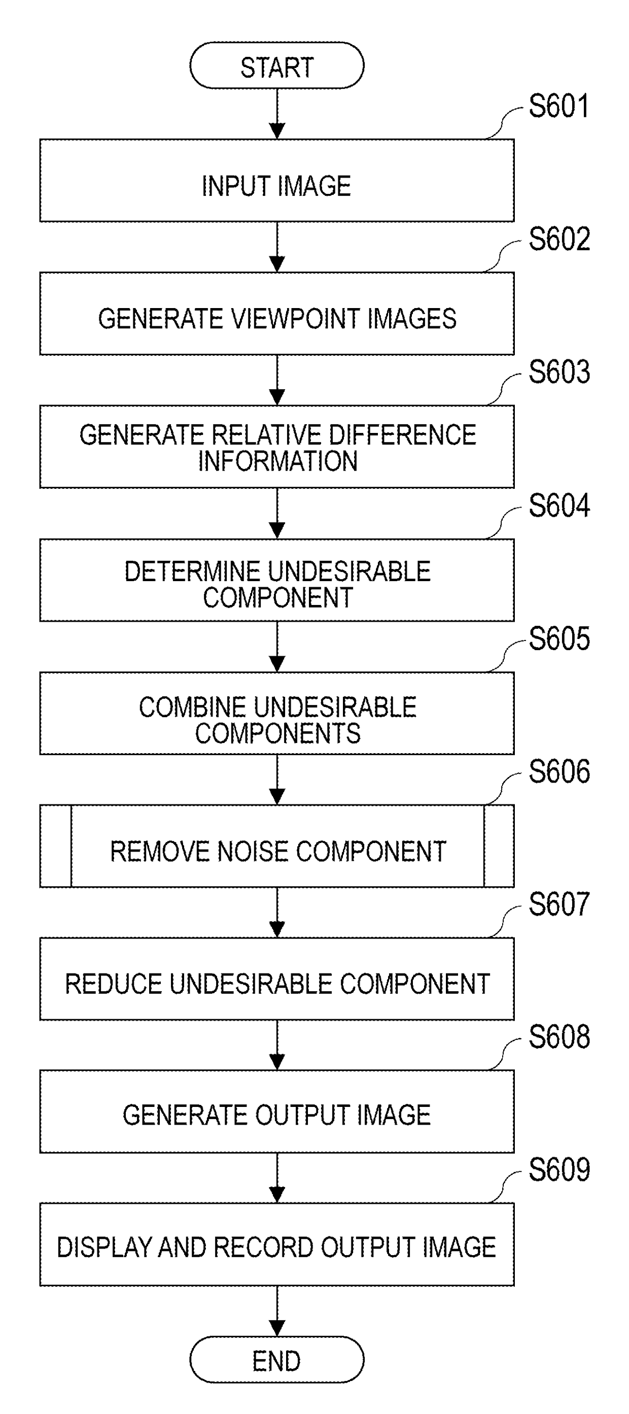
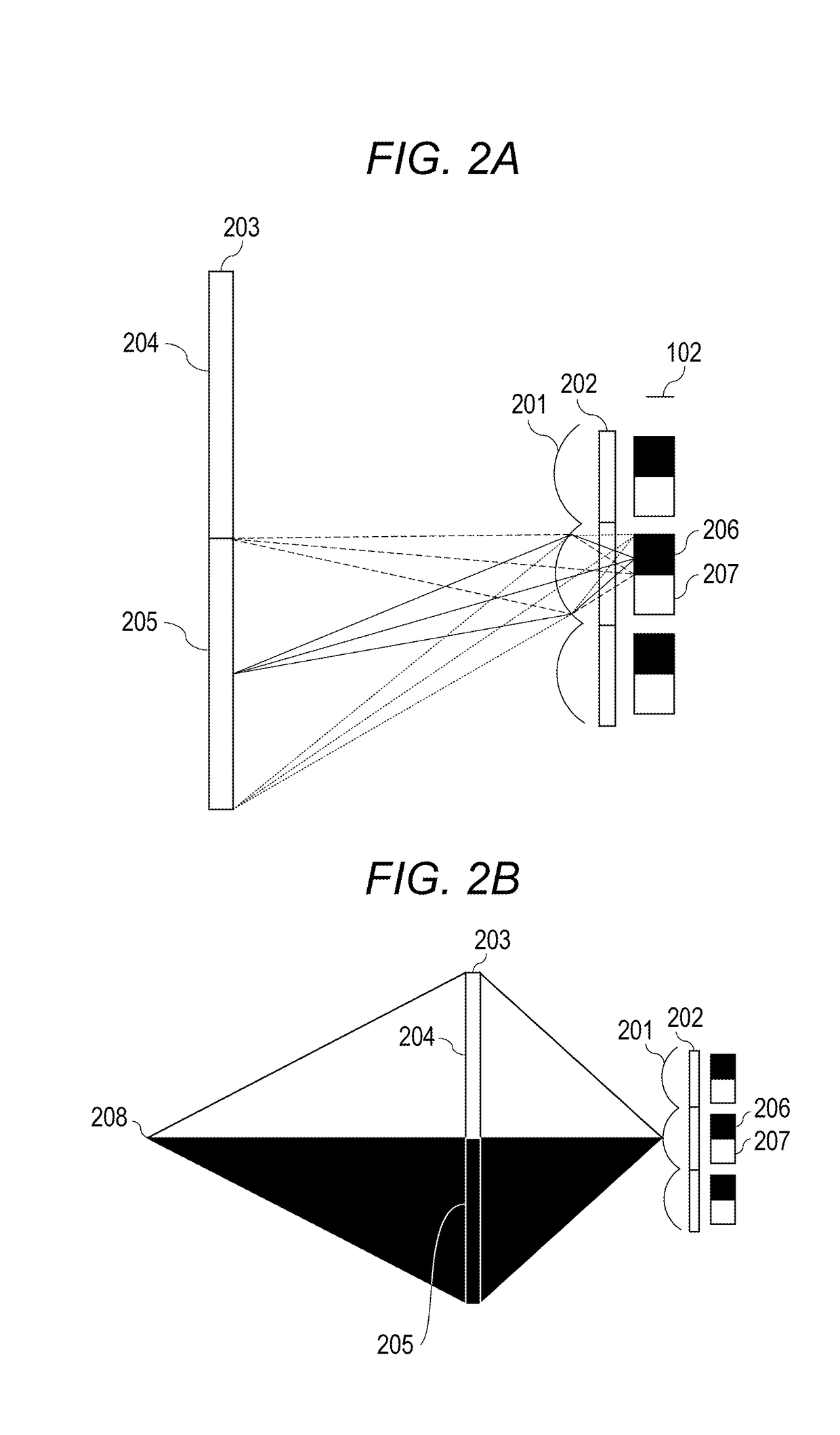
[0017]An image capture apparatus used in the present exemplary embodiment is capable of generating a plurality of viewpoint images. The image capture apparatus includes an image capturing system that guides a plurality of amounts of luminance flux, which has passed through different regions of the pupil of the optical system, to different light-receiving units (pixels) in the image capture element so as to photoelectrically convert the amounts of luminance flux.

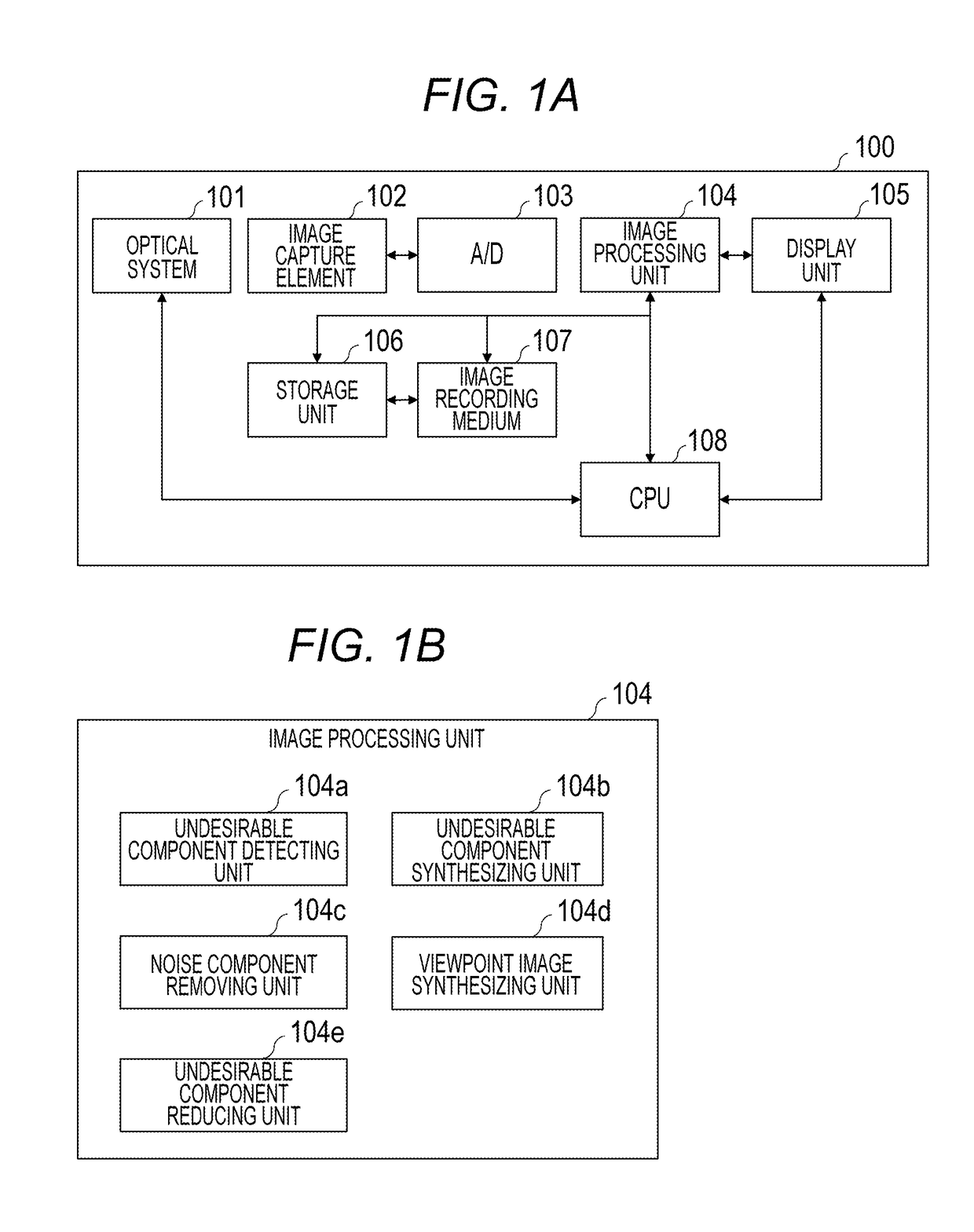
[0018]FIG. 1A is a block diagram of the configuration of an image capture apparatus 100 of an image processing apparatus according to the present exemplary embodiment. An optical system 101 focuses (collects) the luminance flux from an object (not illustrated) on an image capture element 102. The image capture element 102 includes a photoelectric conversion device such as a Charge Coupled Device (CCD) sensor or a Complementary Metal Oxide Semiconductor (CMOS) sensor. In the present exemplary embodiment, the luminance flux fro...

second exemplary embodiment

[0054]Next, a second exemplary embodiment of the present disclosure will be described. In the first exemplary embodiment, the noise component is subtracted from the undesirable components calculated from a plurality of viewpoint images. On the other hand, in the present exemplary embodiment, the noise component is subtracted from each of the viewpoint images, and then the undesirable components of the viewpoint images are calculated. Thus, the undesirable components from which the noise component has been reduced or removed are calculated.

[0055]The basic configuration of the image capture apparatus of the present exemplary embodiment is similar to the image capture apparatus 100 of the first exemplary embodiment described with reference to FIG. 1A, and thus the descriptions will be omitted.

[0056]FIG. 8 is a block diagram of the configuration of an image processing unit 104 of the present exemplary embodiment. The processing units of the image processing unit 104 and processes perfor...


PUM


Abstract

An image processing apparatus includes an image obtaining unit configured to obtain a plurality of viewpoint images, a detecting unit configured to detect a first undesirable component of the viewpoint images according to relative difference information that is a difference between the viewpoint images, a noise information obtaining unit configured to obtain noise information of the viewpoint images, a calculation unit configured to calculate a second undesirable component by subtracting noise from the first undesirable component according to the first undesirable component and the noise information, and a reducing unit configured to reduce the second undesirable component of an image formed based on the viewpoint images.

Description

BACKGROUNDField of the Disclosure[0001]The present disclosure relates to an image processing method for improving the image quality of a captured image.Description of the Related Art[0002]When an image capture apparatus such as a camera captures an image, a part of the light entering the optical system is sometimes reflected on the boundary face of a lens or on a member holding the lens and reaches the image pickup plane as an undesirable light. The undesirable light that has reached the image pickup plane appears in the captured image as an undesirable component such as a ghost or flare. Japanese Patent Laid-Open No. 2011-205531 discloses a method that detects a ghost by comparing a plurality of viewpoint images.[0003]The method of Japanese Patent Laid-Open No. 2011-205531 detects a ghost by calculating the difference between the viewpoint images. When each viewpoint image has a large amount of noise, the accuracy of the detection of a ghost is decreased.SUMMARY[0004]What is needed...

Claims


Application Information

Patent Timeline
Patent Type & Authority Applications(United States)
IPC IPC(8): H04N5/359G06T3/40H04N13/02H04N5/357H04N5/341
CPCH04N5/3597H04N5/3572G06T3/4015H04N13/0217H04N5/3415H04N13/218H04N13/232H04N2013/0088H04N23/951H04N25/615H04N25/626H04N23/843H04N25/41
Inventor YAMANAKA, YOHEI
Owner CANON KK
Why Eureka
Try Eureka