Step cavity low-frequency ultrasonic atomizing nozzle having vortex flow impeller

a low-frequency ultrasonic and atomizing nozzle technology, which is applied in the direction of spray nozzles, liquid spraying apparatus, spraying apparatus, etc., can solve the problems of large droplet size and poor uniformity, and achieve the effect of reducing the total pressur

Active Publication Date: 2020-04-30
JIANGSU UNIV
View PDF3 Cites 4 Cited by
  • Summary
  • Abstract
  • Description
  • Claims
  • Application Information

AI Technical Summary

Benefits of technology

The present invention relates to a nozzle for atomizing liquid in a high-speed air flow. The technical effects of the invention include improved resonance frequency, increased fluid turbulence, and more uniform droplet distribution. The nozzle has a ladder-shaped resonant cavity with serrated protrusions that enhance fluid instability and a zigzag inner surface to facilitate fluid resonance. The nozzle also has an annular groove and an exciter to further crack and refine fog droplets. These features result in increased sound pressure levels and better discharge of compressed gas.

Problems solved by technology

Piezoelectric ultrasonic atomization nozzles have the advantages of small and uniform droplets, but its small amount of atomization, only used for small-scale atomization cultivation; the advantages of two-phase atomization nozzle is the large amount of atomization, the disadvantage is that droplet size is large and poor uniformity.

Method used


Image

  • Step cavity low-frequency ultrasonic atomizing nozzle having vortex flow impeller
  • Step cavity low-frequency ultrasonic atomizing nozzle having vortex flow impeller
  • Step cavity low-frequency ultrasonic atomizing nozzle having vortex flow impeller

Examples


Embodiment Construction

[0025]The present invention will be further described below with reference to the accompanying drawings and specific embodiments, but the scope of protection of the present invention is not limited thereto.

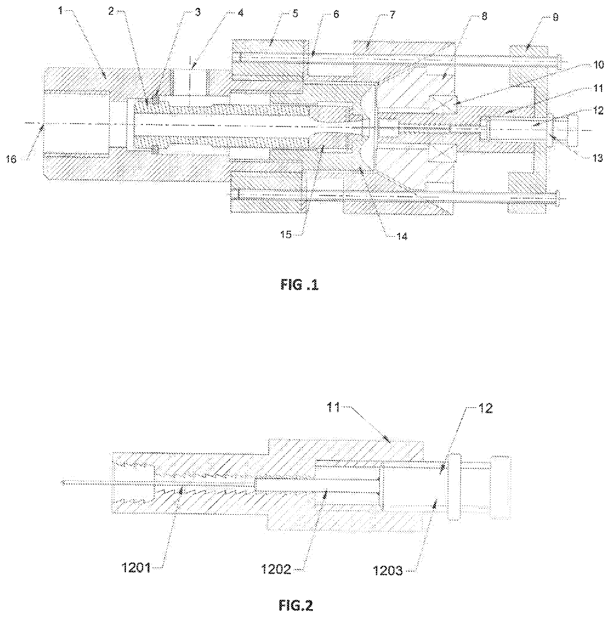
[0026]As shown in FIG. 1, the step chamber type low frequency ultrasonic atomizing nozzle with a swirlable vortex impeller according to the present invention mainly comprises an air intake casing 1, a water inlet casing 2, a Laval valve core 15, and a fixed cap 14. The adjustable base 5, the conical rectification sleeve 7, the vortex impeller 8, the stepped resonance tube 11, the adjustment plunger 12, the positioning screw 6, and the second base 9 are formed. The inlet sleeve 1 has an inlet in the center and a liquid inlet hole in the sidewall; the through hole at the center of the cone-shaped rectifier sleeve 7 has a cylindrical section and a conical section; the second base 9 is A screw hole is formed in the central position, and a rectangular groove is formed on one end surfac...


PUM


Abstract

A step cavity low-frequency ultrasonic atomizing nozzle includes an air inlet casing tube, a water inlet casing tube, a de Laval valve, a fixed cap, a first adjustable base, a tapered rectification sleeve, a vortex flow impeller, a stepped resonance tube, an adjustment plunger, a positioning screw, and a second base. The adjustment plunger is located within a second step hole of the stepped resonance tube, and the axial position thereof is adjustable. The vortex flow impeller is fixed on the stepped resonance tube via a bearing, and an outer tapered surface thereof attaches to an inner tapered surface of the tapered rectification sleeve.

Description

TECHNICAL FIELD[0001]The invention relates to a two-phase atomizing atomization nozzle, in particular to a step cavity type low-frequency ultrasonic atomization nozzle with a swirlable vortex impeller.BACKGROUND TECHNIQUE[0002]At present, in the field of aeroponics, the atomization methods used mainly include piezoelectric ultrasonic atomization and mechanical atomization (such as two-phase atomization of better droplets). Piezoelectric ultrasonic atomization nozzles have the advantages of small and uniform droplets, but its small amount of atomization, only used for small-scale atomization cultivation; the advantages of two-phase atomization nozzle is the large amount of atomization, the disadvantage is that droplet size is large and poor uniformity. Therefore, optimizing the design of the two-phase flow nozzle to fully utilize the energy of the high-speed air flow, it is imperative to develop an atomization nozzle that can generate fine and uniform high-quality droplets and a larg...

Claims


Application Information

Patent Timeline
Patent Type & Authority Applications(United States)
IPC IPC(8): B05B17/06B05B1/34
CPCB05B17/0615B05B1/341B05B17/0669B05B7/0433B05B7/2424B05B7/10B05B17/0692
Inventor GAO, JIANMINMA, JUNLONG
Owner JIANGSU UNIV
Why Eureka
Try Eureka