Apparatus, aircraft and method for moving a wing tip device away from a load-alleviating configuration

a technology of wing tip device and load-alleviating configuration, which is applied in the direction of influencers by generating vortices, airflow influencers, transportation and packaging, etc., can solve the problem of not being able to create a sufficiently large aerodynamic effect, and achieves a smooth movement, asymmetrical, and asymmetrical effect.

Active Publication Date: 2020-04-30
AIRBUS OPERATIONS LTD
View PDF0 Cites 2 Cited by
  • Summary
  • Abstract
  • Description
  • Claims
  • Application Information

AI Technical Summary

Benefits of technology

[0007]By providing such an airflow channel, aspects of the present invention recognise that aerodynamic forces may be used to urge the wing tip device back into the flight configuration. This may enable the load capacity of an actuator (for returning the wing tip device to the flight configuration) to be reduced. This may even remove the need for the actuator all together. A reduction in load capacity or removal of an actuator, may enable significant weight and / or space savings.
[0031]In other embodiments, the apparatus need not comprise any damper and / or biasing member. Indeed, in some embodiments the wing tip device may be entirely free to rotate when the restraining assembly is in the releasing mode (i.e. there may be substantially no other resistive forces acting to prevent rotation once the restraining force is removed). When the wing tip device is free to rotate in this manner, it may be referred to as ‘coasting’ or being arranged to ‘coast’. For some embodiments of the invention, having such an arrangement have been found to be especially beneficial. In such embodiments, the centre of gravity of the wing tip device may be positioned such that no substantive shear loads are passed into the wing tip and to ensure the flutter speed is sufficiently high. Aspects of the present invention may be especially advantageous in embodiments in which there is no damper and / or biasing member because it may enable the wing tip device to more readily return to the flight configuration under the aerodynamic forces when the channel is in the open state.

Problems solved by technology

It has been found that a deployable control surface alone (e.g. a spoiler) tends not to be able to create a sufficiently large aerodynamic effect to achieve this.

Method used


Image

  • Apparatus, aircraft and method for moving a wing tip device away from a load-alleviating configuration
  • Apparatus, aircraft and method for moving a wing tip device away from a load-alleviating configuration
  • Apparatus, aircraft and method for moving a wing tip device away from a load-alleviating configuration

Examples


Embodiment Construction

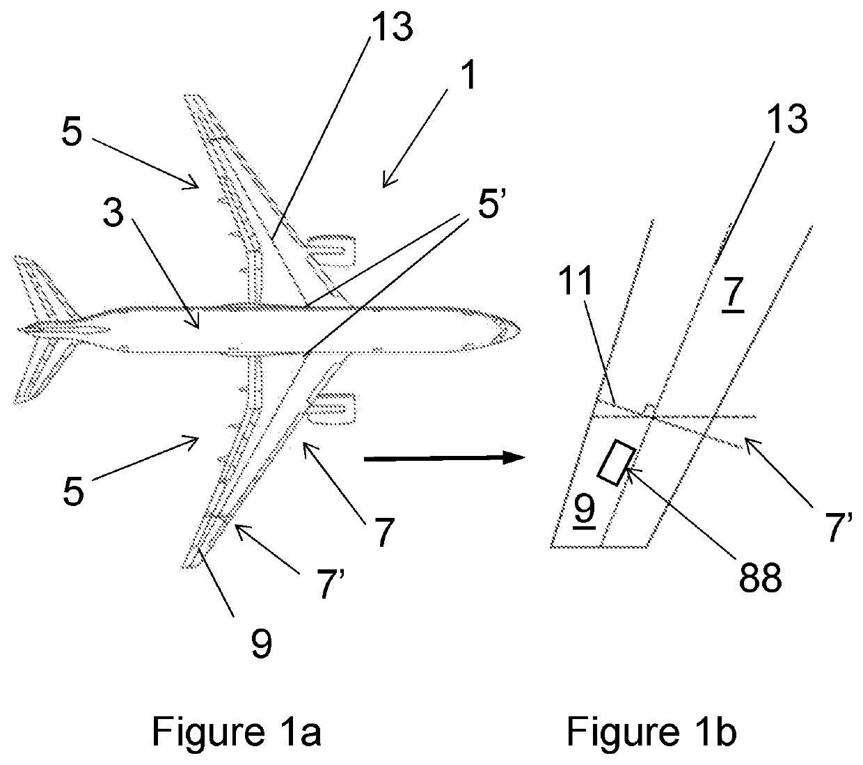
[0058]FIG. 1a is a plan view of an aircraft 1 according to a first embodiment of the invention. The aircraft comprises a central fuselage 3 and two main wings 5 extending outwardly from respective wing roots 5′.

[0059]Each wing 5 comprises a fixed wing 7 extending from the root 5′ to the tip 7′ (shown in close up in FIG. 1b). At the tip 7′ of the fixed wing 7, the wing 5 also comprises a moveable wing tip device 9, in the form of a planar wing tip extension. The wing tip device 9 is rotatably mounted about a hinge 11 that is orientated perpendicular to the swept mid-chord axis 13. This hinge 11, is thus non-parallel to the line of flight direction (the line of flight direction being shown in FIG. 1b for comparison).

[0060]The wing tip device 9 also comprises an airflow channel 88 to which reference is made in more detail in FIG. 4 onwards.

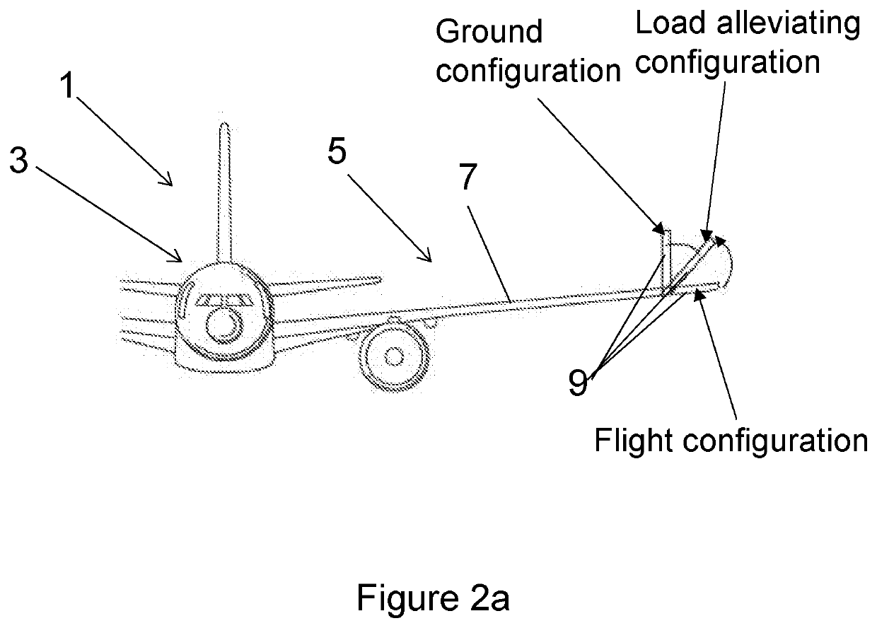
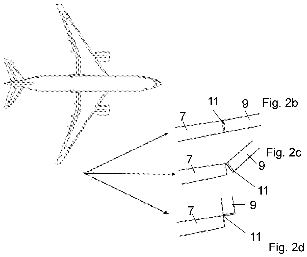
[0061]Referring now to FIGS. 2a-2c, the wing tip device 9 is rotatable about the hinge 11 from a flight configuration to a load-alleviating configur...


PUM


Abstract

An aircraft (1) including a fixed wing (7) and a wing tip device (9) moveably mounted thereon. The wing tip device (9) is movable from a load-alleviating configuration to a flight configuration. The wing tip device includes an airflow channel (88) extending between respective apertures (83, 84) on the upper surface and lower surface of the wing tip device. The channel (88) is configurable between an open state in which air can flow through the channel and a closed state in which the airflow through the channel (88), via the apertures (83, 84), is blocked. The channel (88) is configured such that when the wing tip device (9) is in the load-alleviating configuration and the channel (88) is in the open state, the aerodynamic loading on the wing tip device in flight urges the wing tip device towards the flight configuration.

Description

[0001]The present disclosure relates to aircraft with moveable wing tip devices, and methods of moving a wing tip device.[0002]Embodiments of the present invention concern aircraft with a fixed wing and a movable wing tip device at the tip thereof. More particularly, but not exclusively, embodiments of the invention concern aircraft comprising a movable wing tip device that is moveable from a load-alleviating configuration to a flight configuration. Embodiments of the invention also concern methods of moving a mounted wing tip device from the load-alleviating configuration to a flight configuration.BACKGROUND OF THE INVENTION[0003]Aircraft with moveable wing tip devices attached to fixed wings are known to those skilled in the art. The wing tip devices are typically used to allow load-alleviation during flight, for example, in the event of wind gusts. Typically, large loads cause the wing tip device to move from a flight configuration in which the wing tip device is effectively a co...

Claims


Application Information

Patent Timeline
Patent Type & Authority Applications(United States)
IPC IPC(8): B64C23/06B64C21/08B64C5/08
CPCB64C23/076B64C21/08B64C5/08B64C23/072B64C9/146B64C3/546B64C2003/543Y02T50/40Y02T50/10B64C3/38B64C21/02B64C23/065
Inventor O'ROURKE, CIARAN
Owner AIRBUS OPERATIONS LTD
Why Eureka
Try Eureka