

Window regulator and method of assembling the same
- Summary
- Abstract
- Description
- Claims
- Application Information
AI Technical Summary
Benefits of technology
Problems solved by technology
Method used
Image

Examples
Embodiment Construction
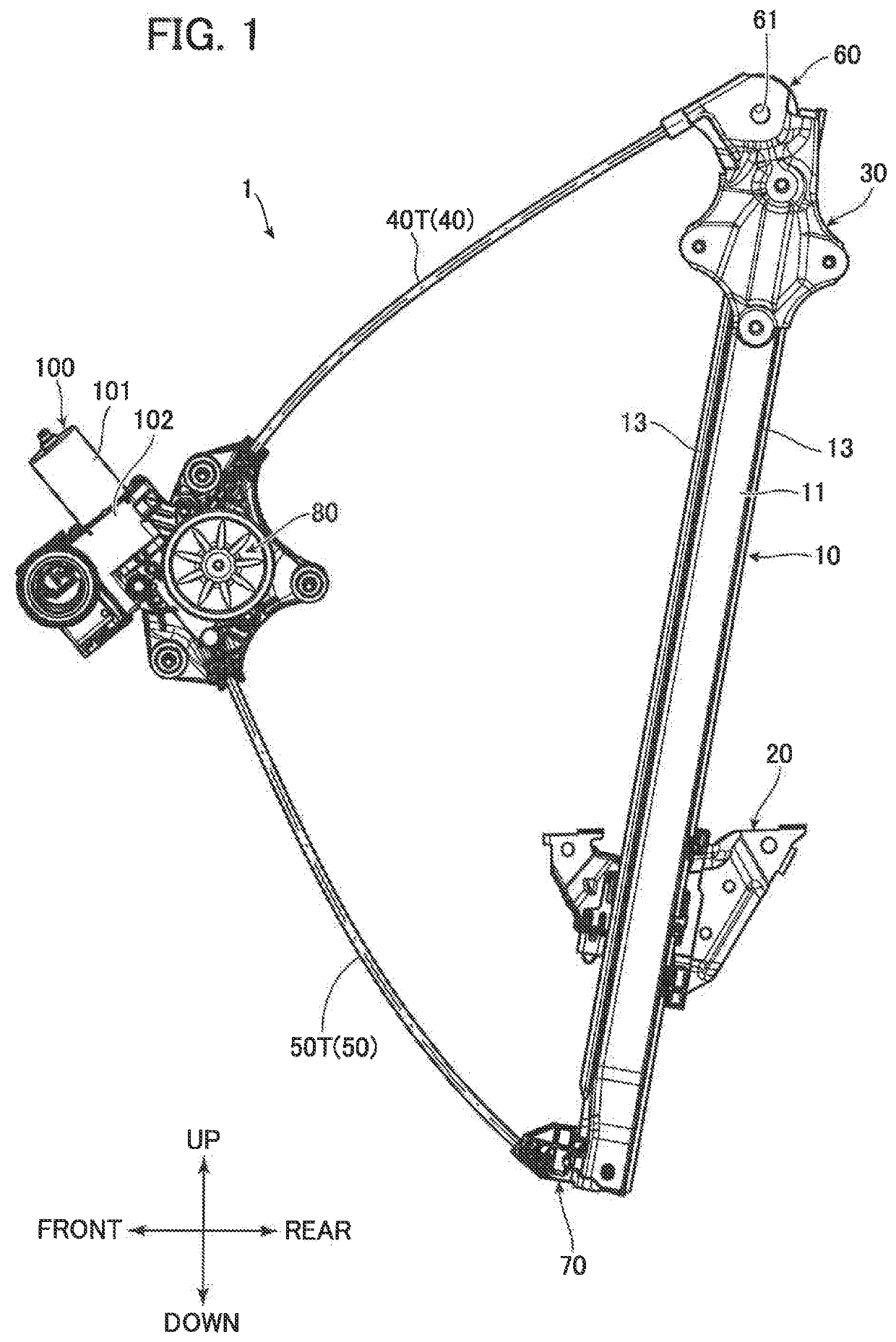
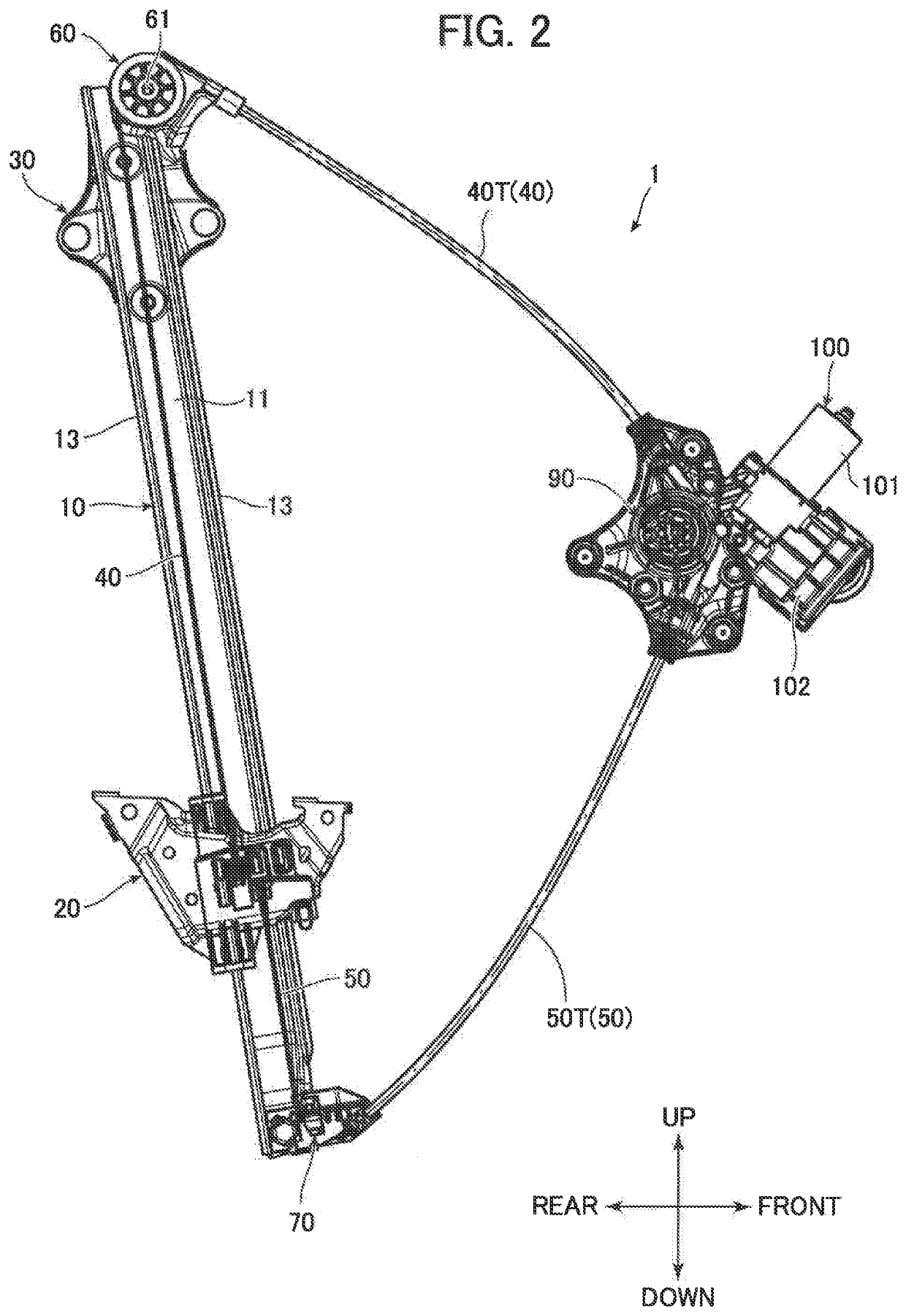
[0027]A window regulator 1 according to an embodiment of the invention will be described in details with reference to FIGS. 1 to 11. In the following description, directions (such as up, down, front, rear, inside, and outside) are indicated with respect to arrow directions illustrated in the drawings.
1>
[0028]As illustrated in FIGS. 1 and 2, the window regulator 1 has a guide rail 10 and a slider 20. The guide rail 10 extends in a vertical direction which is an operation direction of a window glass (not shown). The slider 20 is installed to a window glass (not shown) and is guided to the guide rail 10 along the vertical direction (operation direction). The guide rail 10 is fixed to an inner panel (not shown) of a vehicle using a bracket 30.
[0029]One end of each of a pair of wires 40 and 50 for driving the slider 20 with respect to the guide rail 10 in the vertical direction (operation direction) is connected to the slider 20.
[0030]A guide pulley 60 provided in the upper end of the gu...
PUM
 Abstract
Description
Claims
Application Information