Transfer method and transfer apparatus

Active Publication Date: 2020-04-30
AU OPTRONICS CORP
View PDF0 Cites 2 Cited by
  • Summary
  • Abstract
  • Description
  • Claims
  • Application Information

AI Technical Summary

Benefits of technology

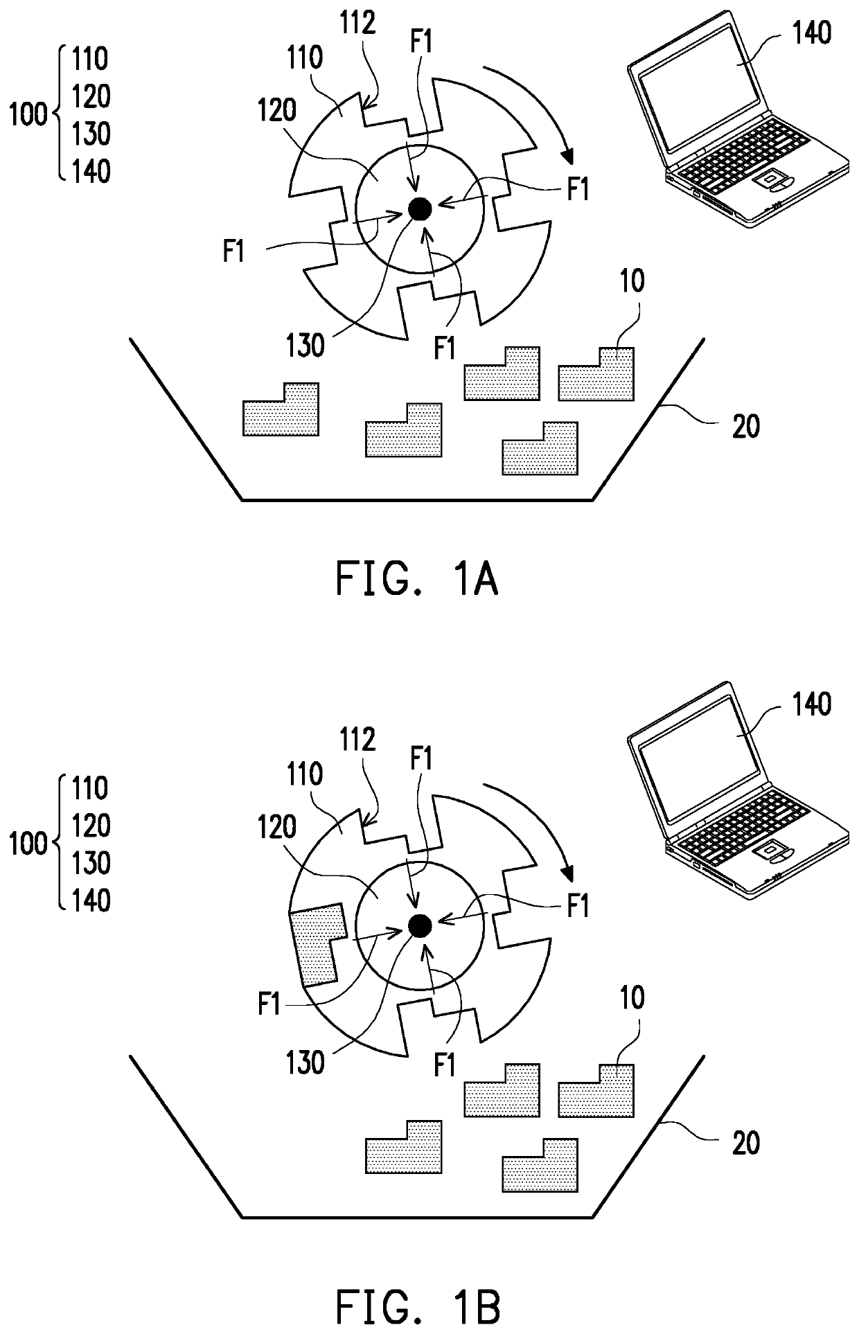
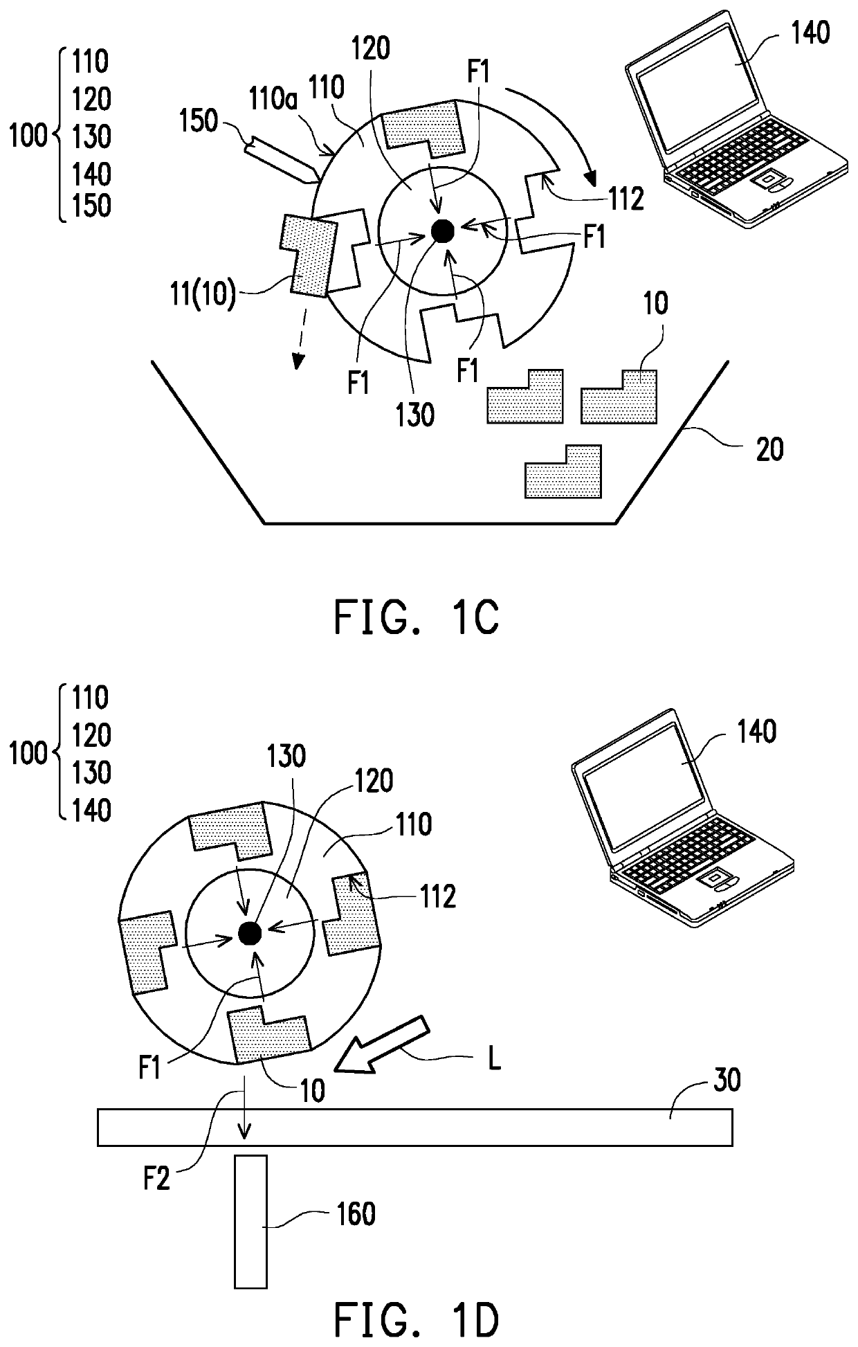
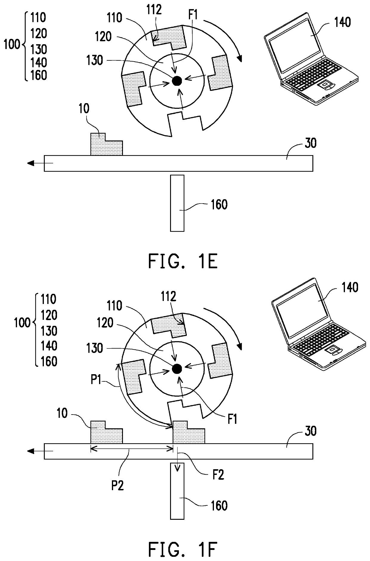
This patent provides a transfer method and apparatus that can increase the manufacturing yield of micro-devices. The invention accurately positions the micro-devices during transfer using a balance of magnetic force and mechanical force, and subsequently transfers them to the receiving device through gravure printing or other similar methods. This results in a higher manufacturing yield as the micro-devices are accurately aligned with the receiving device.

Problems solved by technology

However, if the transfer process is to be expanded in scale, the transfer method using the elastic transfer head having the transfer bumps faces issues of insufficient manufacturing yield, inaccuracy, and difficulty in mass production.

Method used


Image

  • Transfer method and transfer apparatus
  • Transfer method and transfer apparatus
  • Transfer method and transfer apparatus

Examples


Embodiment Construction

[0020]Descriptions of the invention are given with reference to the exemplary embodiments illustrated with accompanied drawings, wherein same or similar parts are denoted with same reference numerals. Wherever possible, the same reference numbers are used in the drawings and the description to refer to the same or like parts.

[0021]It should be understood that when an element such as a layer, film, region or substrate is referred to as being “on” or “connected to” another element, it can be directly on or connected to the other element, or intervening elements may also be present. In contrast, when an element is referred to as being “directly on” or “directly connected to” another element, there is no intervening element present. As used herein, the term “connected” may refer to physically connected and / or electrically connected. Besides, “electrical connection” or “coupling” may be referred to as an intervening element existing between two elements.

[0022]The term “about,”“approximat...


PUM


Abstract

A transfer method including following steps is provided. A pick-up device having a plurality of caves is provided. A first magnetic force capable of attracting a plurality of micro-devices to move toward the caves of the pick-up device is provided. Given that the first magnetic force is provided, the pick-up device is in contact with the micro-devices, so that the micro-devices are snapped by the caves of the pick-up device. The micro-devices are transferred from the caves of the pick-up device to a receiving device. Besides, a transfer apparatus is also provided.

Description

CROSS-REFERENCE TO RELATED APPLICATION[0001]This application claims the priority benefit of Taiwan application serial no. 107137874, filed on Oct. 26, 2018. The entirety of the above-mentioned patent application is hereby incorporated by reference herein and made a part of this specification.BACKGROUNDTechnical Field[0002]The disclosure relates to a transfer method and a transfer apparatus.Description of Related Art[0003]A mass transfer technology for transferring micro-devices has been applied in the emerging manufacturing process of an electronic device. The manufacturing process of a light-emitting diode (LED) display apparatus is taken as an example. The manufacturing process of the LED display apparatus includes following steps: providing an elastic transfer head having a plurality of transfer bumps; providing an LED array; having the transfer bumps of the elastic transfer head contact with a plurality of LEDs of the LED array and picking up the LEDs; transferring the LEDs to a...

Claims


Application Information

Patent Timeline
IPC IPC(8): H01L21/677H01L33/00B65G47/92
CPCH01L21/67709H01L33/005H01L21/67721B65G47/92H01L33/0095H01L21/67144H01L21/683H05K13/0408H01L25/0753H01L24/95H01L2224/83815H01L2224/95133H01L2224/95136H01L2221/68363H01L2221/68368H01L2221/68381H01L2224/83191H01L2224/83192H01L2224/291H01L2224/83224H01L2224/75261H01L2224/75253H01L2224/75651H01L2224/75655H01L2224/95101H01L2224/95115H01L2224/97H01L24/83H01L21/6835H01L2924/00014H01L2924/014H01L2224/83
Inventor NIU, TZU-LING
Owner AU OPTRONICS CORP
Why Eureka
Try Eureka