EMC Filter and Use Thereof

a filter and filter body technology, applied in the field of filter components, can solve the problems of requiring too many electrical components and excessive dimensions of filters based on typical lc sections, and achieve the effect of improving properties

Active Publication Date: 2020-04-30
EPCOS AG
View PDF4 Cites 9 Cited by
  • Summary
  • Abstract
  • Description
  • Claims
  • Application Information

AI Technical Summary

Benefits of technology

[0011]The filter component described specifies a compact and simple component that effectively rejects the second harmonic. In particular, the harmonic is shorted in a simple manner by the resonant circuit. A large number of capacitors, for example, for a first and a second LC filter stage and a large inductance of the first and second LC filter stages can be avoided. This allows a low-noise signal to be made available using a simple component having small dimensions.
[0013]According to one exemplary embodiment, a fundamental frequency of the wireless power transmission is between 81 kHz and 90 kHz. Preferably, the fundamental frequency is 85 kHz. The resonant circuit is designed and arranged for attenuation of the second harmonic. In particular, the resonant circuit is designed and set up for attenuation of a frequency of 170 kHz. Preferably, the resonant frequency of the resonant circuit is 170 kHz. In this way, the second harmonic can be effectively attenuated in a simple manner.
[0015]According to one exemplary embodiment, an equivalent resistance of the resonant circuit is less than or equal to the impedance of the at least one second capacitor. In particular, the resonant circuit has only a small number of capacitors. In this way, the impedance at 170 kHz can be reduced.
[0016]According to one exemplary embodiment, the resonant circuit has a quality factor Q. Preferably, Q is ≤100, particularly preferably, Q is ≤50. The low quality factor means that a bandwidth from 162 kHz to 180 kHz can be covered. The second harmonic can be effectively rejected.
[0017]According to one exemplary embodiment, the inductance is designed such that the resonant frequency is 170 kHz. This allows the second harmonic to be effectively rejected at a fundamental frequency of approximately 85 kHz.

Problems solved by technology

Filters based on typical LC sections have excessively large dimensions, in particular, and require too many electrical components.

Method used


Image

  • EMC Filter and Use Thereof
  • EMC Filter and Use Thereof
  • EMC Filter and Use Thereof

Examples


Embodiment Construction

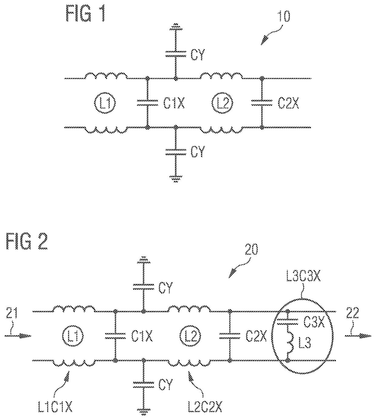
[0028]FIG. 1 shows a circuit diagram for a filter component 10 based on the prior art. The filter component 10 is an EMC filter.

[0029]The filter component 10 has a first LC filter stage L1C1X. The first LC filter stage L1C1X has a first inductance L1 and a first capacitor arrangement C1X. The capacitor arrangement C1X has at least one capacitor C1, but preferably a multiplicity X of capacitors C1.

[0030]The filter component 10 further has a second LC filter stage L2C2X. The second LC filter stage L2C2X is connected in series with the first LC filter stage L1C1X. The second LC filter stage L2C2X has a second inductance L2 and a second capacitor arrangement C2X. The capacitor arrangement C2X has at least one capacitor C2, but preferably a multiplicity X of capacitors C2.

[0031]Instead of the first and second LC filter stages, the filter component 20 can alternatively have a filter structure or an arbitrary number of filter structures L, C, LC, CLC, LCLC (not depicted explicitly). The fi...


PUM


Abstract

A filter component such as an EMC filter and a method for using an filter component are disclosed. In an embodiment, a filter component includes a resonant circuit having an inductance and at least one capacitor that is connected in series with the inductance, wherein the resonant circuit is designed and arranged for attenuating harmonics in a longwave band.

Description

[0001]This patent application is a national phase filing under section 371 of PCT / EP2017 / 053902, filed Feb. 21, 2017, which claims the priority of German patent application 10 2016 103 447.9, filed Feb. 26, 2016, each of which is incorporated herein by reference in its entirety.TECHNICAL FIELD[0002]The present invention relates to a filter component, particularly an EMC filter. The invention further relates to the use of a filter component.BACKGROUND[0003]In wireless power transmission (WPT), electric power is transmitted contactlessly from one object to another. The frequency of the wireless power transmission is typically between 81 kHz and 90 kHz, particularly is approximately 85 kHz, for applications in the automotive sector. Following wireless power transmission, the alternating signal needs to be rectified and subsequently forwarded to the high voltage (HV) bus. The signal on the HV bus then needs to be in the limited harmonic range from the 85 kHz rectification or conditionin...

Claims


Application Information

Patent Timeline
Patent Type & Authority Applications(United States)
IPC IPC(8): H02M1/12H02M1/44H02J50/12H02J3/01
CPCH02M1/126H02J50/12H02J3/01H02M1/44
Inventor BECK, FABIAN
Owner EPCOS AG
Why Eureka
Try Eureka