Separation System

a separation system and separation technology, applied in the field of separation systems, can solve the problems of labor-intensive and time-consuming processes, and achieve the effects of reducing time and expense, high efficiency, and high separation efficiency

Active Publication Date: 2020-05-07
FMC TECH INC
View PDF0 Cites 3 Cited by
  • Summary
  • Abstract
  • Description
  • Claims
  • Application Information

AI Technical Summary

Benefits of technology

[0036]The skid mounted separation system described herein provides a single system that allows operators to go straight into production from the drillout phase of operation, which greatly reduces the time and expense which otherwise would be required to configure and rig-up different systems for the different phases. During the drillout phase, the addition of a high efficiency desander upstream of the skid mounted system enables the separation system to employ high efficiency separation components in order to increase oil recovery, produce cleaner water, and meet custody transfer conditions at the outlet of the skid. By meeting custody transfer conditions at the outlet of the skid, the gas, oil and water can be piped or shipped directly to storage or processing facilities without the need for intermediate processing apparatuses or steps on site, which reduces the time and overall expense of the operation.

Problems solved by technology

This process may involve disassembling and reconnecting different devices that are specifically sized to handle the different proportions of sand, water and well fluids which are produced at each phase, which is a labor intensive and time consuming process.

Method used


Image

  • Separation System
  • Separation System
  • Separation System

Examples


Embodiment Construction

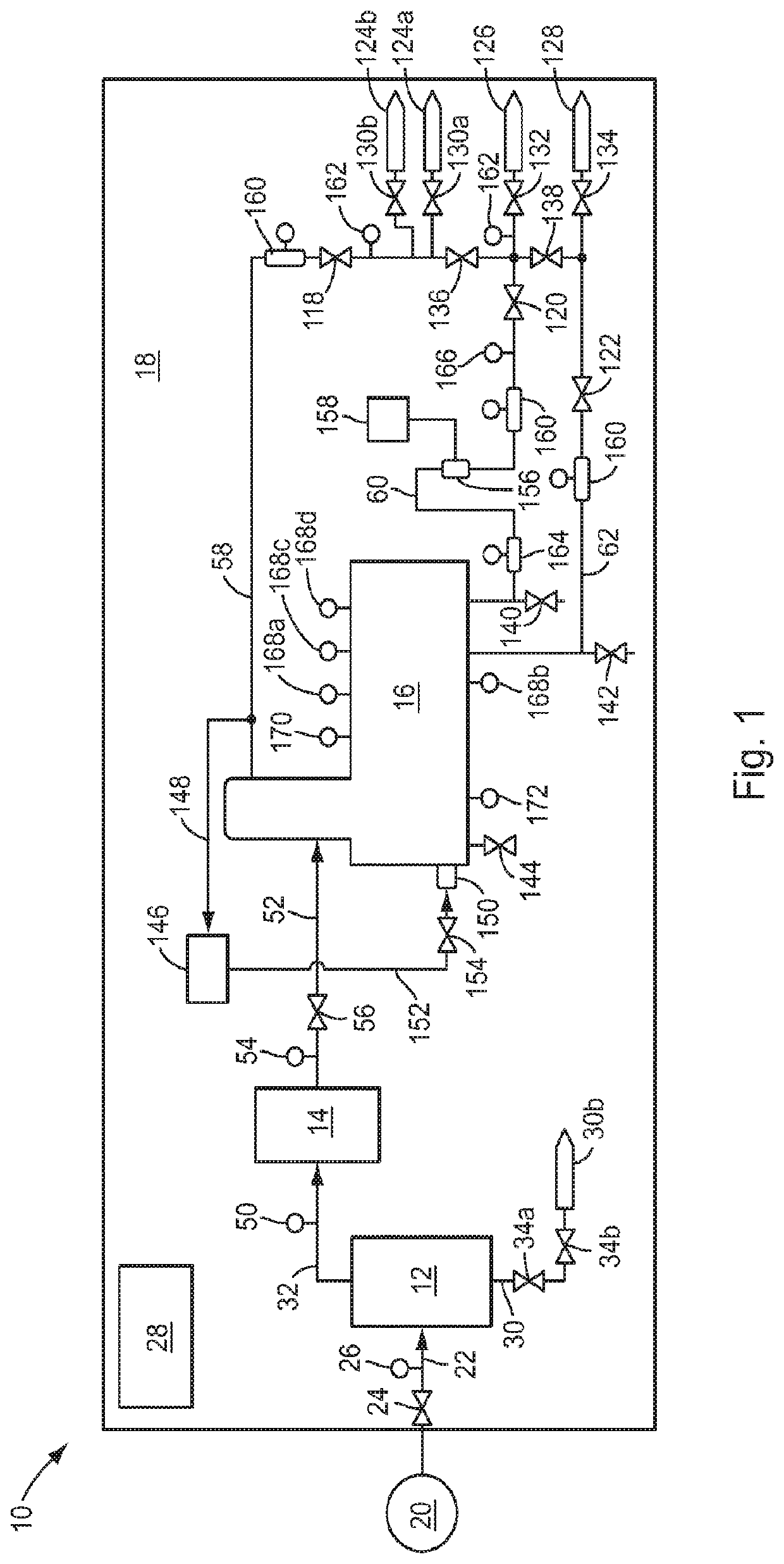
[0044]A schematic representation of an illustrative embodiment of the separation system of the present disclosure is shown in FIG. 1. The separation system of this embodiment, which is indicated generally by reference number 10, includes a desander 12 which is connected to a choke manifold 14 that in turn is connected to a multiphase separator 16. The desander 12, choke manifold 14 and separator 16 are mounted on a common transportable support surface, such as a skid 18. The skid 18 enables the separation system 10 to be easily transported to the well site by, e.g., a trailer truck (not shown). In addition, mounting the desander 12, choke manifold 14 and separator 16 together on the skid 18 allows the connections between these components and their associated equipment to be made up prior to delivery of the separation system 10 to the well site, which will reduce the time required to set up and connect the separation system to other well site equipment.

[0045]In use, the separation sy...


PUM

PropertyMeasurementUnit
distanceaaaaaaaaaa
pressureaaaaaaaaaa
flow rateaaaaaaaaaa

Abstract

A system for separating a multiphase well stream into a solids fraction, a water fraction, an oil fraction and a gas fraction includes a transportable support surface; a solids separator which is mounted on the support surface and is configured to receive the multiphase well stream and separate the well stream into a first heavy fraction primarily comprising the solids fraction and a first light fraction primarily comprising the gas, oil and water fractions; and a multiphase fluid separator which is mounted on the support surface and includes a first separator section and a second separator section which is positioned vertically below and connected directly to the first separator section. The first separator section is configured to receive the first light fraction and separate the first light fraction into a second light fraction primarily comprising the gas fraction and a second heavy fraction primarily comprising the oil and water fractions. The second separator section is configured to receive the second heavy fraction and separate the second heavy fraction into a third light fraction primarily comprising the oil fraction and a third heavy fraction primarily comprising the oil fraction.

Description

[0001]The present disclosure is directed to a separation system for desanding a multiphase well fluid and for separating the well fluid into its separate gas, oil and water fractions.BACKGROUND OF THE INVENTION[0002]Hydraulic fracturing, or “fracking”, is a common technique for enhancing the extraction of oil and gas from a hydrocarbon well. Fracking involves injecting a high pressure fracking fluid into the well bore in order to create fissures in the hydrocarbon formation through which the oil or gas may flow. The fracking fluid usually includes a mixture of water, chemicals and proppant, such as sand. In some well fracking operations, hundreds of thousands of pounds of sand and millions of gallons of water may be used.[0003]After the fracking operation is completed, much of the fracking water and sand are recovered. First, the well bore is drilled out to remove the fracking sand and any plugs which may be present in the well bore. Then, the well is allowed to flow back in order t...

Claims


Application Information

Patent Timeline
Patent Type & Authority Applications(United States)
IPC IPC(8): E21B43/34B01D17/02B01D17/12B01D21/30B01D17/04
CPCB01D17/12B01D17/045B01D17/0211B01D2221/04B01D21/30E21B43/34B01D17/0214B01D17/00B01D19/0042E21B43/35
Inventor MALONE, RYANRASMUSSEN, ERIC JOSEPHCIPRICK, KELLYCHAN, ISABELVAN ASPEREN, VICTORBAAREN, SANDER GUIDO
Owner FMC TECH INC
Why Eureka
Try Eureka