Antenna module and communication device

a communication device and antenna module technology, applied in the direction of antenna details, polarised antenna unit combinations, antennas, etc., can solve the problems of hindering the improvement of communication quality and the difficulty of improving the isolation between adjacent antenna elements, so as to improve the communication quality of such a communication device and improve the communication quality of an antenna module

Active Publication Date: 2020-05-14
MURATA MFG CO LTD
View PDF0 Cites 7 Cited by
  • Summary
  • Abstract
  • Description
  • Claims
  • Application Information

AI Technical Summary

Benefits of technology

[0035]The improvement of the communication quality of such a communication device is also achieved by providing the above-described antenna module in the communication device.
[0036]According to the present disclosure, the improvement of the communication quality of an antenna module that includes a patch antenna array and the communication quality of a communication device are achieved.

Problems solved by technology

In the above configuration, however, the polarizations of electric fields that are excited when the same radio-frequency signal is fed to radiation conductors of the adjacent antenna elements are the same as each other, and thus, it is difficult to improve the isolation between the adjacent antenna elements.
Thus, in an antenna module that uses such a patch antenna array, for example, as a result of undesirable signals leaking to a radio frequency integrated circuit (RFIC) and so forth that are electrically connected to the patch antenna array, the improvement of the communication quality is hindered.

Method used


Image

  • Antenna module and communication device
  • Antenna module and communication device
  • Antenna module and communication device

Examples


embodiment

[1. Configuration of Antenna Module]

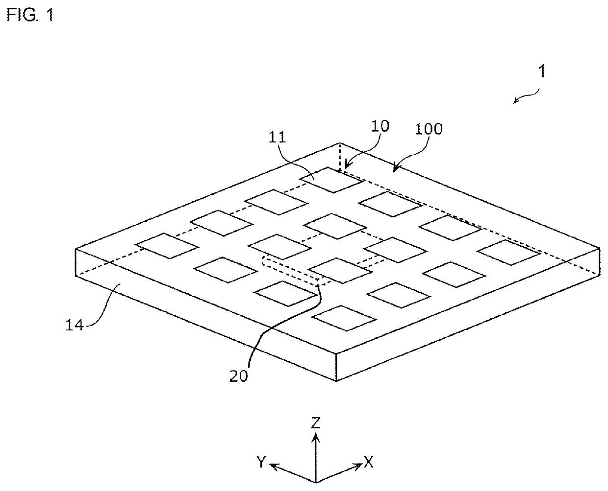
[0049]FIG. 1 is an external perspective view of an antenna module 1 according to an embodiment of the present disclosure.

[0050]In the following description, a thickness direction of the antenna module 1 will be referred to as the Z-axis direction, and directions that are perpendicular to the Z-axis direction and that are perpendicular to each other will be referred to as the X-axis direction and the Y-axis direction. In addition, the positive z-axis side will be defined as the top surface side of the antenna module 1. However, in the actual usage situation, there is a case where the thickness direction of the antenna module 1 is not parallel to the vertical direction, and thus, the direction toward the top surface of the antenna module 1 is not limited to being parallel to the upward direction.

[0051]The antenna module 1 that is illustrated in FIG. 1 is compatible with two types of polarized waves both at the time of transmission and reception and ...


PUM


Abstract

An antenna module (1) includes an antenna array (100) that includes a plurality of radiation conductors (11) arranged at regular intervals in or on a dielectric substrate (14) and an RFIC (20) that is provided in or on the dielectric substrate (14) and that performs signal processing on a transmission signal transmitted by the antenna array (100) or a reception signal received by the patch antenna array (100). Each of the plurality of radiation conductors (11) has a transmission feeding point from which the transmission signal is transmitted to the RFIC (20) and a reception feeding point at which the reception signal is received from the RFIC (20).

Description

[0001]This is a continuation of International Application No. PCT / JP2018 / 020359 filed on May 28, 2018 which claims priority from Japanese Patent Application No. 2017-138859 filed on Jul. 18, 2017. The contents of these applications are incorporated herein by reference in their entireties.BACKGROUND OF THE DISCLOSUREField of the Disclosure[0002]The present disclosure relates to an antenna module and a communication device, and more particularly to a configuration that includes a patch antenna array.Description of the Related Art[0003]As a dual-polarized patch antenna array (a two-polarized antenna array), there is disclosed a patch antenna array in which antenna elements that are adjacent to each other form a mirror image (see, for example, Patent Document 1). In other words, in the adjacent antenna elements, two feeding points are set at positions that are line-symmetrical to each other. With this configuration, cross polarization and side lobe can be suppressed.[0004]Patent Documen...

Claims


Application Information

Patent Timeline
Patent Type & Authority Applications(United States)
IPC IPC(8): H01Q21/06H01Q1/22H01Q23/00H04B1/38
CPCH04B1/38H01Q23/00H01Q21/065H01Q1/2283H01Q3/36H01Q21/24
Inventor ONAKA, KENGOYAMADA, YOSHIKITAKAYAMA, KEISEIMORI, HIROTSUGU
Owner MURATA MFG CO LTD
Why Eureka
Try Eureka