Communication apparatus and communication method

a communication apparatus and communication method technology, applied in the direction of electrical apparatus, radio transmission, power management, etc., can solve the problems of increasing the difficulty of the access point side to determine which station secures the resource, and the inability of the point to set the appropriate transmission power of the station, so as to reduce the interference and reduce the reception power difference between the stations in the access point.

Active Publication Date: 2020-05-21
PANASONIC INTPROP MANAGEMENT CO LTD
View PDF0 Cites 0 Cited by
  • Summary
  • Abstract
  • Description
  • Claims
  • Application Information

AI Technical Summary

Benefits of technology

This approach effectively reduces carrier interference and maintains the reception signal within the A / D conversion dynamic range, improving system throughput by dynamically adjusting target reception power values based on station reception qualities.

Problems solved by technology

However, in the above-described MU transmission with the random access instructed by the random access control signal (TF-R), it is difficult for the access point side to determine which station secures the resource by the random access.
Thus, the access point cannot set appropriate transmission power of the station that transmits the UL response signal by the random access.
This leads a problem that a reception power difference between the stations in the access point increases and a reception signal in the access point does not fall within the dynamic range of A / D conversion, or a problem that the Signal to Interference plus Noise Ratio (SINR) decreases due to interference between the stations.

Method used


Image

  • Communication apparatus and communication method
  • Communication apparatus and communication method
  • Communication apparatus and communication method

Examples


embodiment 1

[Summary of Communication System]

[0059]A communication system according to this embodiment includes an access point (communication apparatus) 100 and a station 200. The access point 100 is an access point applicable to 11ax, and the station 200 is a station applicable to 11ax.

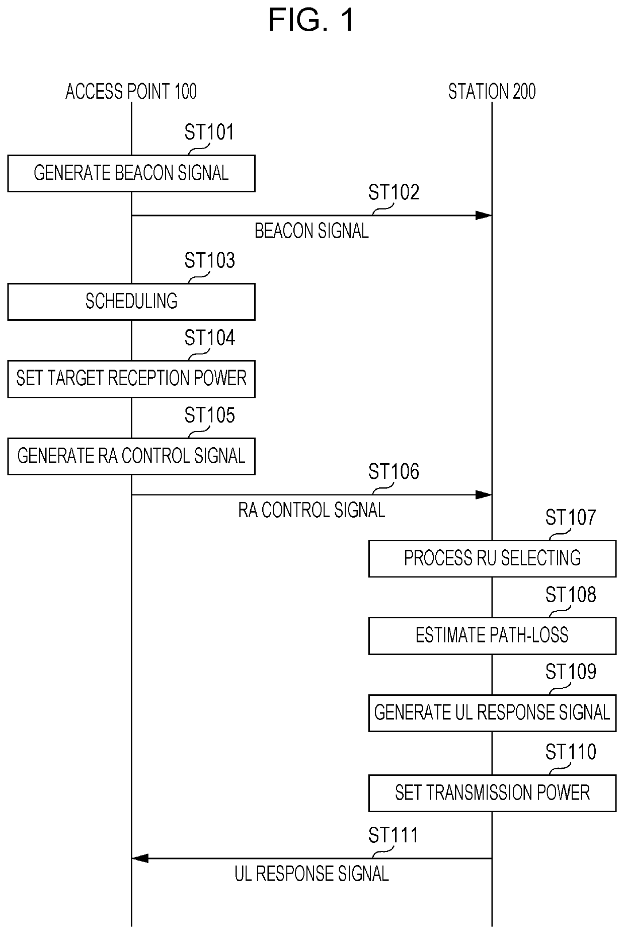
[0060]FIG. 1 illustrates a sequence of processing in the communication system according to this embodiment.

[0061]In FIG. 1, the access point 100 generates a beacon signal (step (hereinafter, represented as “ST”) 101).

[0062]The beacon signal includes transmission power of the access point 100. Specifically, equivalent isotropic radiated power (hereinafter, EIRP) of the access point 100 is set as the transmission power. In general, the EIRP is broadcast determined based on antenna gain in the maximum radiated direction of a directional antenna. Thus, when the station 200 performs later-described path-loss estimation and transmission power setting based on the EIRP, a difference may occur between actual reception ...

embodiment 2

[0231]As described above, the access point notifies the station of the target reception power value using the random access control signal and performs the transmission power control at the station side, and thus the reception power difference between the stations in the access point can be reduced when the access point receives a signal in which signals from the multiple stations are multiplexed via UL MU-MIMO or OFDMA.

[0232]However, an 11ax-compliant station has low performance of the transmission power control. For example, among the 11ax-compliant stations, there may be a station that can change the transmission power for only few stages and a station that has no function of the transmission power control in some cases. Thus, in each station, regardless of the calculation of the transmission power based on the target reception power value and the like provided as notification, the response signal may not be transmitted with the transmission power satisfying the target reception ...

embodiment 3

[0256]As described above, the station stops the transmission of the response signal that cannot satisfy the target reception power depending on the situation, and thus the reception power difference between the stations in the access point can be reduced regardless of the performance of the station. However, depending on the setting of the target reception power value, stopping the transmission may increase the number of the stations that have significantly decreased opportunities for transmitting the response signal.

[0257]Thus, in this embodiment, a method of preventing the significant decrease of the opportunities for transmitting the response signal of a specific station, such as a station with a low capability in controlling the transmission power, by changing the target reception power value and the like at every transmission when the random access control signals are successively transmitted.

[0258]FIG. 24 is a block diagram that illustrates a configuration of an access point 4...


PUM


Abstract

A communication apparatus includes: signal generation circuitry which, in operation, generates a control signal including a target reception power value regarding a target value of a reception power for the communication apparatus to receive an uplink (UL) response frame transmitted by each of one or more terminal stations, the control signal being a trigger frame that solicits transmission of the UL response frame from each of the one or more terminal stations; and transmission circuitry which, in operation, transmits the generated signal.

Description

BACKGROUND1. Technical Field[0001]The present disclosure relates to a communication apparatus and a communication method to perform uplink transmission power control.2. Description of the Related Art[0002]In Task Group ax of the Institute of Electrical and Electronics Engineers (IEEE) 802.11 Working Group, a technical specification of IEEE 802.11ax (hereinafter, 11ax) is being developed as a next standard that would replace 802.11ac. In 11ax, a multi-user transmission method (hereinafter, MU transmission) based on the orthogonal frequency-division multiple access (OFDMA) and the multi user-multi input multi output (MU-MIMO) is expected to be introduced to uplink (UL).[0003]In a UL MU transmission procedure, an access point (also called a base station) transmits a control signal as a trigger for an uplink signal to multiple stations (also called STAs) within the area covered by the access point. Based on the control signal, a station, which transmits the uplink signal, transmits an U...

Claims


Application Information

Patent Timeline
Patent Type & AuthorityApplications(United States)
IPC IPC(8): H04W52/18H04W52/32H04W52/58H04W52/24H04W52/14
CPCH04W52/325H04W52/58H04B7/0452H04W52/247H04W52/362H04W74/08H04W52/18H04W52/146H04W52/262H04W52/367H04W52/50
InventorTAKATA, TOMOHUMIURABE, YOSHIOIWAI, TAKASHI
OwnerPANASONIC INTPROP MANAGEMENT CO LTD