[0023]Next, a core-sheath structured filament according to an embodiment of the present invention will be described.
[0024]It is to be noted that the present invention is not limited only to the following embodiment.
Core-Sheath Structure
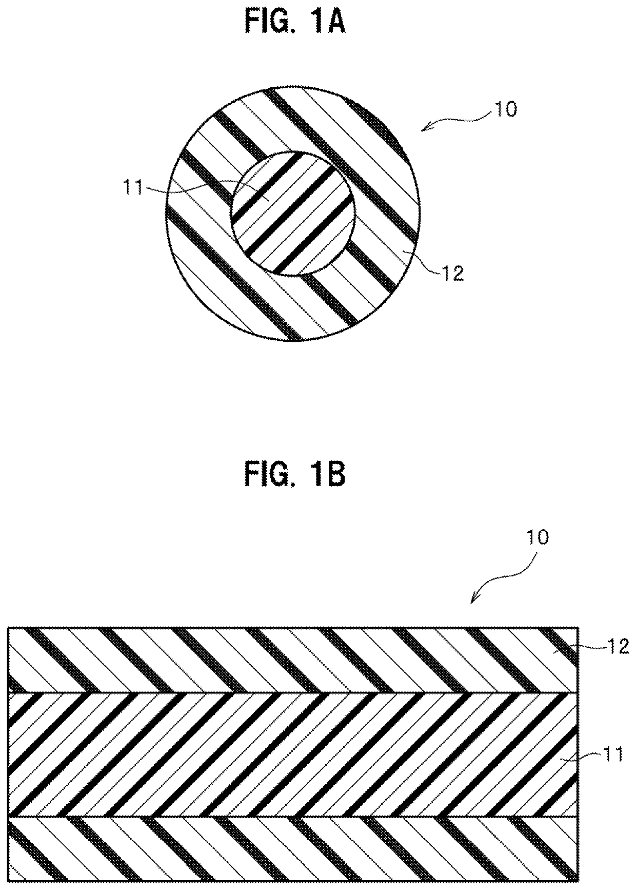
[0025]FIG. 1A illustrates a transverse sectional view showing a round cross-section of a core-sheath composite fiber 10 of this embodiment, and FIG. 1B illustrates a vertical sectional view showing a cross-section in a long-side direction of the core-sheath composite fiber 10 of this embodiment.
[0026]The core-sheath composite fiber 10 of this embodiment includes a core member 11, and a sheath member 12 that is wrapped around the core member 11. The core-sheath composite fiber 10 is formed by extrusion. Each of the core member 11 and the sheath member 12 of this embodiment has an external shape with a round cross-section. Note that the external shape of the core member is not limited to such a round cross-section but may be an irregular cross-section provided with multiple projections, for instance.
[0027]A proportion between the core member 11 and the sheath member 12 in the transverse section taken in a direction perpendicular to a length direction as shown in FIG. 1A is set preferably in a range from 99:1 to 1:99 or more preferably in a range from 90:10 to 10:90. It is possible to improve rigidity by increasing a percentage of the core member. On the other hand, it is possible to improve adhesion by increasing a percentage of the sheath member.
[0028]The core-sheath composite fiber 10 may adopt an eccentric structure. Nevertheless, the core member 11 is preferably arranged substantially at the center of the sheath member 12 as shown in FIGS. 1A and 1B. By arranging the core member 11 substantially at the center of the sheath member 12, it is possible to prevent exposure of the core members 11 from the sheath members 12 when the core-sheath composite fibers 10 are pressed into a composite material 100 (see FIG. 3) or the like. By preventing the exposure of the core members 11, it is possible to firmly bind the sheath members 12 together and thus to firmly mold into the composite material 100 or the like.
Rigidity Of Core-Sheath Composite Fiber
[0029]A possible application of the core-sheath composite fiber 10 is for reinforcement of a fuel tank of an automobile, for example. An outer skin of the fuel tank or the like frequently comprises polyethylene. Accordingly, a possible operation to improve a welding property of the core-sheath composite fiber 10 to the outer skin is to include polyethylene in the sheath member 12.
[0030]However, polyethylene is a substance which generally has a difficulty in establishing a bond with another substance, and it is hard to achieve firm adhesion between the core member 11 and the sheath member 12 that contains polyethylene. Accordingly, the use of polyethylene in the core member 11 may lead to deterioration in rigidity of the core-sheath composite fiber 10 due to separation of the sheath member 12 from the core member 11. In particular, in a case where the core-sheath composite fibers 10 is pressed into a composite material 100 (see FIG. 3) or the like, the separation of the sheath member 12 from the core member 11 is more prone to occur if a difference in melting point between the core member 11 and the sheath member 12 is increased in order to facilitate the molding. Hence, the aforementioned deterioration in rigidity becomes more problematic. The molding of the composite material 100 will be described later.
[0031]Given the situation, our researchers attempted to realize the core-sheath composite fiber 10 that has a large difference in melting point between the core member 11 and the sheath member 12 while having the high rigidity as well, by using modified polyethylene prepared by adding an unsaturated functional group to polyethylene so as to establish hydrogen bonding between the functional group and the sheath member 12.
[0032]FIG. 2 illustrates a schematic diagram of a device used in a rigidity measurement test for the core-sheath composite fiber 10.
[0033]The core-sheath composite fiber 10 prepared by adopting polyamide as the core member 11 and adopting maleic acid-modified polyethylene as the sheath member 12 is used as an example. Meanwhile, a core-sheath composite fiber prepared by adopting polyamide as the core member 11 and adopting polyethylene as the sheath member 12 is used as a comparative example.
[0034]Each of the two core-sheath composite fibers 10 is fixed onto two rollers 2 as shown in FIG. 2 and a force at 0.5 N is applied thereto from top to bottom, that is, in a direction of an arrow in FIG. 2. Displacements due to stretch occurring in the respective core-sheath composite fibers 10 are measured and compared with each other.
[0035]As a result of the measurement, the displacement of the core-sheath composite fiber 10 of the comparative example was 2.140 mm. On the other hand, the displacement of the core-sheath composite fiber 10 of the example was 1.762 mm. The comparison of the two fibers reveals that the rigidity of the core-sheath composite fiber 10 of the example prepared by adopting maleic acid-modified polyethylene as the sheath member 12 is improved by 17% as compared to the core-sheath composite fiber 10 of the comparative example prepared by adopting unmodified polyethylene as the sheath member 12.
[0036]Based on the above-mentioned result, polyamide is used as a main component of the core member 11 of the core-sheath composite fiber 10 and modified polyethylene is used as a main component of the sheath member 12 thereof. Note that the main component of the core member 11 means a content in an amount of 40% by mass or more with respect to total components of the core member 11. The main component of the sheath member 12 means a content in an amount of 40% by mass or more with respect to total components of the sheath member 12.
Materials Of Core-Sheath Composite Fiber
[0037]A difference in melting point between the core member 11 and the sheath member 12 is equal to or above 170° C. or preferably equal to or above 180° C.
[0038]With the difference in melting point equal to or above 170° C., a failure of melting the core member 11 at the same time as melting the sheath member 12 is less likely to occur, and it is easier to press into the composite material 100 (see FIG. 3) or the like by using the core-sheath composite fibers 10. Note that the molding of the composite material 100 will be described later.
[0039]Accordingly, an appropriate combination of polyamide as the main component of the core member 11 and modified polyethylene as the main component of the sheath member 12 of this embodiment are selected such that the difference in melting point between these components becomes equal to or above 170° C.
Core Member
[0040]Now, details of respective components of the core member and the sheath member will be described below.
[0041]While polyamide constituting the main component of the core member 11 of this embodiment is not limited to a particular composition as long as the difference in melting point between polyamide and modified polyethylene serving as the main component of the sheath member 12 is equal to or above 170° C., this polyamide preferably has high rigidity in light of its intended use as the reinforcement member. Examples of available polyamide compositions include polyamide 6, polyamide 12, polyamide 66, and so forth.
Sheath Member
[0042]Modified polyethylene constituting the main component of the sheath member 12 of this embodiment is not limited to a particular composition as long as such a composition can be melted in the course of blow molding into the fuel tank or the like being a target for the welding, and as far as the composition has a melting point that provides the difference in melting point from the polyamide composition being the main component of the core member 11, which is equal to or above 170° C., and the composition is also capable of establishing the hydrogen bonding with the polyamide composition.
[0043]An example of a method of obtaining such modified polyethylene is called graft modification. This is a method of attaching an unsaturated functional group to a carbon radical that is generated by cleaving the carbon-hydrogen bond in polyethylene. The carbon radical can be generated by electron beam irradiation or ionizing radiation irradiation, or by use of radical generators such as organic and inorganic peroxides.
[0044]The functional group to be used for the modification can be selected from a carboxyl group, an amino group, a hydroxyl group, a silanol group, and the like. Among these functional groups, the hydroxyl group is preferable and the carboxyl group is more preferable.
[0045]Examples of a structural unit having the functional group include structural units deriving from compounds such as unsaturated carboxylic acid or a derivative thereof, an ethylene-based unsaturated compound having a hydroxyl group, an ethylene-based unsaturated compound having an amino group, and an organic silicon compound having a vinyl group. Among these structural units, the ethylene-based unsaturated compound having the hydroxyl group is preferable and the unsaturated carboxylic acid or the derivative thereof is more preferable.
[0046]Examples of the unsaturated carboxylic acid or the derivative thereof include an unsaturated compound having one or more carboxylic groups, an ester of alkyl alcohol and a compound having a carboxylic group, an unsaturated compound having one or more carboxylic anhydride groups, etc.
[0047]Examples of the unsaturated carboxylic acid include acrylic acid, maleic acid, fumaric acid, tetrahydrophthalic acid, itaconic acid, citraconic acid, crotonic acid, isocrotonic acid, Nadic (registered trademark) acid (endo-cis-bicyclo[2.2.1]hept-5-ene-2,3-dicarboxylic acid), etc.
[0048]Examples of the derivative of the unsaturated carboxylic acid include maleimide, maleic anhydride, citraconic anhydride, monomethyl maleate, dimethyl maleate, glycidyl maleate, etc.
[0049]These unsaturated carbonic acids and/or the derivatives thereof can be used alone or in combination of two or more of them. Among them, acrylic acid is preferable and maleic anhydride is more preferable in light of its high reactivity.
Composite Molding
[0050]FIG. 3 illustrates a schematic diagram of the composite material 100 formed from the multiple core-sheath composite fibers 10.
[0051]The multiple core-sheath composite fibers 10 are arranged into a bundle as shown in an upper part of FIG. 3 and the sheath members 12 are melted by heating. Then, the core-sheath composite fibers 10 are subjected to molding by means of cold pressing. Thus, the composite material 100 having a polygonal cross-section can be obtained as shown in a lower part of FIG. 3.
[0052]When the core-sheath composite fibers 10 are formed into the composite material 100 as described above, it is easier to form such composite materials 100 into a sheet 101 (see FIG. 4A) than forming the sheet 101 directly from the core-sheath composite fibers 10.
[0053]The heating method is not limited to a particular method, and methods such as heating with an IR (infrared) heater, heating with hot-air, heating with a hot plate, and the like are conceivable. Among them, the IR heater or the hot-air heating is preferable from the viewpoints of low cost and simplicity.
[0054]While the methods involving the IR heater and the hot-air heating have the low-cost benefits on one hand, these methods face a difficulty in temperature control because a difference in temperature is prone to occur due to a difference in distance from a heat source. Nonetheless, according to the core-sheath composite fibers 10 of this embodiment, the difference in melting point between the core member 11 and the sheath member 12 is equal to or more than 170° C. Hence, the core members 11 are less likely to be melted even if the temperature of the sheath members 12 near the heat source may exceed the required temperature as a consequence of continuous heating until the melting of the sheath members 12 located away from the heat source. Thus, the core-sheath composite fibers 10 of the present invention can be formed into the composite material 100 easily at low costs without requiring precise temperature control as a consequence of using the inexpensive measures such as the IR heater and the hot-air heating.
Sheet Molding
[0055]FIG. 4A illustrates a schematic diagram of the sheet 101 formed from the core-sheath composite fibers 10 and FIG. 4B illustrates an enlarged diagram of a cross-section of the sheet 101.
[0056]The sheet 101 shown in FIG. 4A can be formed by arranging the core-sheath composite fibers 10 or the composites 100, and then melting and welding the sheath members 12 therein to one another by heating. As shown in FIG. 4B, in the cross-section of the sheet 101, the core members are arranged in modified polyethylene that is melted and welded together, thus achieving higher strength than a simple resin sheet.
[0057]The above-described sheet 101 can be formed into a cover 102 more easily than forming the core-sheath composite fibers 10 directly into the cover 102 which is closely attached to the outer skin of the fuel tank or the like. The fuel tank or the like generally has a complicated shape, and a high level of workability is an important factor for forming the cover 102 that has an identical shape to the outside of the fuel tank or the like and is capable of being closely attached thereto.
Welding Fuel Tank And Covers Together
[0058]FIG. 5 illustrates a perspective view showing an example of reinforcing a fuel tank with covers formed from the core-sheath composite fibers 10.
[0059]The fuel tank includes a tank body T and two covers 102. Although the tank body T and the covers 102 are separated in FIG. 5, the tank body T and the upper and lower covers 102 are welded in reality in accordance with the following process.
[0060]FIGS. 6 to 8 illustrate schematic diagrams of an apparatus that performs the blow molding.
[0061]First, as shown in FIG. 6, an air suction device starts suction of air through suction holes 44 (arrows in dashed lines) prior to disposing the covers 102. Then, the covers 102 that have been molded already are disposed inside molds 42. The covers 102 have the same shape as the external shape of the tank body T to be molded. The covers 102 are fitted onto the molds 42.
[0062]Next, as shown in FIG. 7, a parison P in a melted state is ejected from a dice 41 in a cylindrical form, for example. Along with the ejection, the right and left molds 42 clamp the discharged parison P. Moreover, simultaneously with this clamping operation, compressed air is blown into the parison P through an air pin 43 (arrows in solid lines) to accomplish the blow molding. The parison P is expanded in this way. The expanded parison P is pressed against the covers 102 (see FIG. 8).
[0063]When the parison P comes into contact with the covers 102, portions of the covers 102 in contact with the parison P are melted by the heat of the parison P. As a consequence, the tank body T (the parison P) and the covers 102 are welded. Here, the temperature of the parison P is set preferably in a range from 160° C. to 190° C. or more preferably in a range from 180° C. to 190° C.
[0064]It is understood that the foregoing description is that of the preferred embodiments of the invention and that various changes and modifications may be made thereto without departing from the spirit and scope of the invention as defined in the appended claims.