
Method for intraoral scanning directed to a method of processing and filtering scan data gathered from an intraoral scanner

a scanning method and scanner technology, applied in the field of intraoral scanning, can solve the problems of creating artefact data, undesired incorporation, and obscuring sections of objects from the view of the wand, so as to facilitate and improve the accuracy of intraoral scanning procedures, and reduce the

Active Publication Date: 2020-06-04
NOBEL BIOCARE SERVICES AG
View PDF0 Cites 13 Cited by
  • Summary
  • Abstract
  • Description
  • Claims
  • Application Information

AI Technical Summary

Benefits of technology

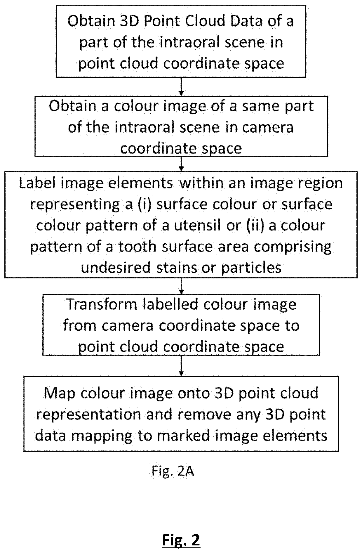
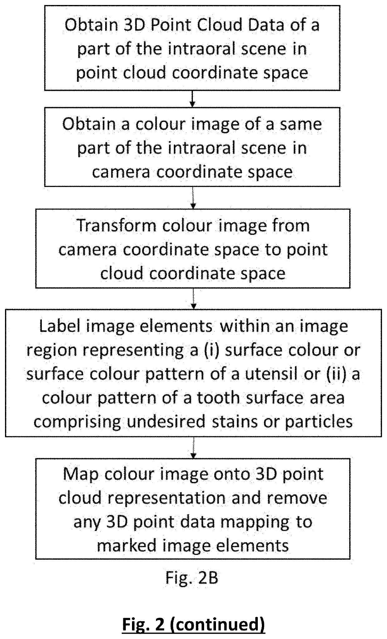
The present invention proposes a method to improve the accuracy of intraoral scanning procedures by eliminating data from objects, such as utensils or stained areas, that were scanned during the procedure. This is achieved by labelling image elements of the colour image in a region with a certain color or pattern and filtering out corresponding cloud data points. The technical effect is the reduction or removal of the influence of data from unwanted objects, resulting in more accurate scanning results.

Problems solved by technology

However, when the wand is positioned at one location of the object scene, some sections of the object scene may be obscured from view of the wand.
Some of these utensils enter the field of view of the intraoral scanning device during data acquisition, which may result in the, typically undesired, incorporation of geometrical data of these utensils in the 3D representation or model.
Furthermore, because these utensils are moving objects, when they are unintentionally incorporated in the scan they may interfere with the stitching process, creating artefactual data.
Other disturbances of the scanning procedure may originate from the moveable intraoral tissues, in particular tongue and cheek.
For instance, during scanning tongue or cheek tissue may move to a location between the scanning tip and the teeth or gingiva resulting in the undesired incorporation of scanning data of this tissue in the 3D model and / or a disturbance of the stitching of the respective scanning data sets.
Such editing of the 3D representation and rescanning is time consuming and lengthens the duration of the scanning procedure for both the patient and the operator.
A further problem in acquiring 3D data of the teeth surfaces is the presence of undesired stains, such as blood stains or particles, such as orthodontic brackets or food particles, on the teeth.
Scanning such stains or particles typically results in the acquisition of incorrect tooth surface data at the positions of these stains or particles.
This also encumbers and lengthens the duration of the scanning procedure.
However, none of the prior art offers an appropriate solution to deal with the undesired presence of utensils or movable tissue.
Nor does any of the prior art documents suggest a way to compensate for the presence of undesired stains or particles on a tooth surface during intraoral scanning.

Method used


Image

  • Method for intraoral scanning directed to a method of processing and filtering scan data gathered from an intraoral scanner
  • Method for intraoral scanning directed to a method of processing and filtering scan data gathered from an intraoral scanner
  • Method for intraoral scanning directed to a method of processing and filtering scan data gathered from an intraoral scanner

Examples


example 1

Scanning System

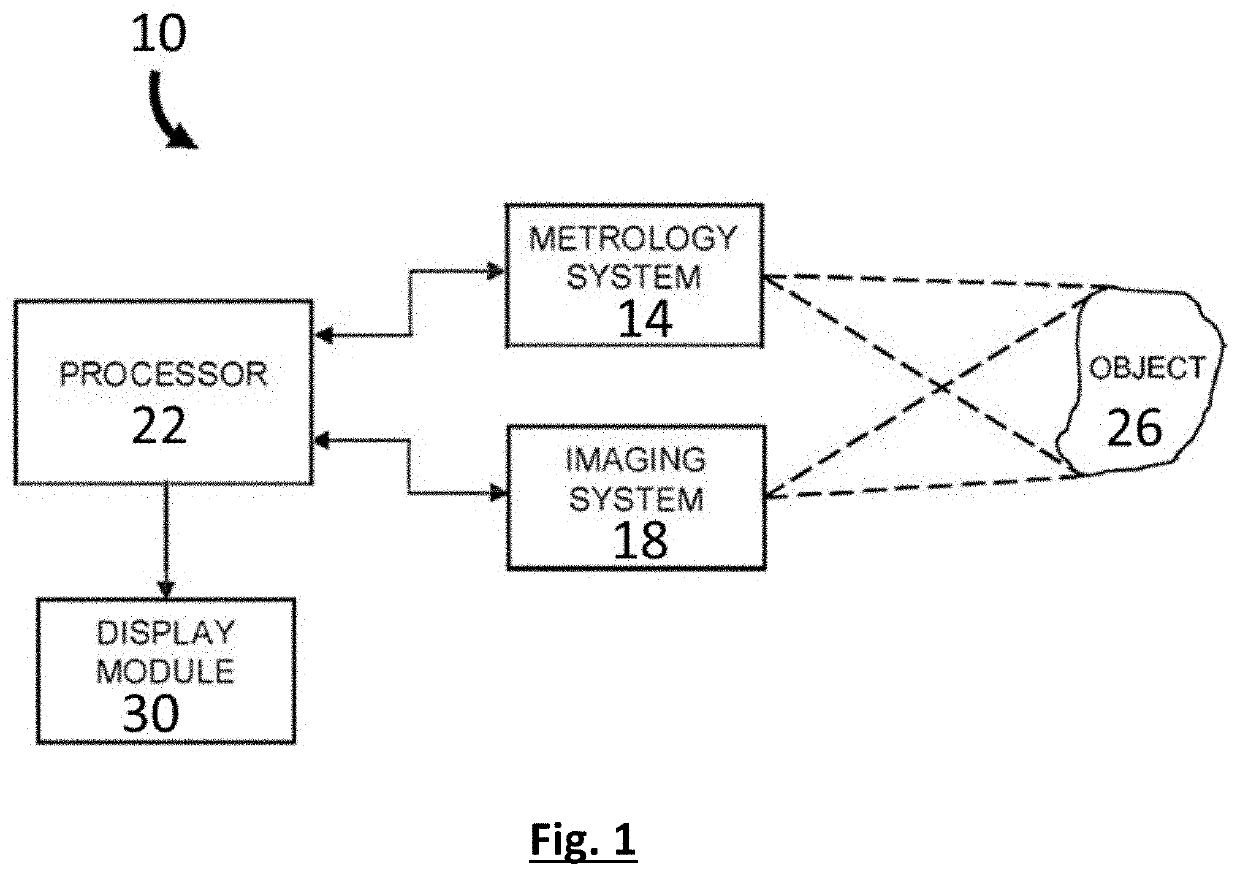
[0093]The intraoral scanning system comprises a harmonic interference fringe 3D metrology device combined with an imaging device comprising a 2D colour camera and a broadband light source mounted in a scanning wand comprising a scanning tip suitable for manoeuvring in the intraoral cavity. The wand is connected to a processing unit operationally linked to a display device. The scanning device allows for sequentially acquiring scanning datasets each comprising 3D point cloud data together with a corresponding colour image of a part of the intraoral cavity within the field of view of the scanning device. By moving the scanner tip over the intraoral scene scanning datasets comprising overlapping spatial data are obtained. The processing unit is coded to filter from the 3D point cloud data any data points data mapping onto image elements of the corresponding colour image that are labelled to represent a surface of which the incorporation in the 3D representation is unwant...

example 2

Geometrical Data from the 3D Point Cloud Data Originating from Green or Blue Utensils

[0094]The processor of an intraoral scanning system according to Example 1 is programmed to label the 2D colour image elements, which has a colour code within a range corresponding to a green and a blue shade as well as the image elements adjacent to such image elements. A colour code [PCr, PCb] of a pixel image element is considered to be within the range of a shade when its colour distance d from a reference shade value [RCr, RCb] is within a range from 0 to 20, wherein d=√{square root over ((RCr−PCr)2+(RCb−PCb)2)}. In this example the reference green and blue shades are defined by the Cr Cb values [49, 101] and [83, 198], respectively.

[0095]The intraoral scanning system is used by an operator who during scanning guides tongue and check tissue with a green gloved finger. The 2D view on the display device indicates that the green fingertip frequently appears within the field of view of the scanning...

example 3

Geometrical Data from the 3D Point Cloud Data Originating from a Utensil Having Surface Colour Pattern

[0097]The processor of an intraoral scanning system according to Example 1 is programmed to label the image elements within a region comprising a blue and green pattern and to filter from the 3D point cloud data any data points that mapped to the labelled image elements of a corresponding colour image. Examples of possible utensil colour patterns are represented in FIG. 6.

[0098]The labelling of the image elements is performed as indicated in the flow chart of FIG. 5. Connected colour image elements having a colour code within a range corresponding to a green (colour0) and a blue shade (colour1) are identified. A colour code [PCr, PCb] of a pixel image element is considered to be within the range of a shade when its colour distance d from a reference shade value [RCr, RCb] is within a range from 0 to 20, wherein d=√{square root over ((RCr−PCr)2+(RCb−PCb)2)}. In this example the refer...


PUM


Abstract

A method and apparatus for generating and displaying a 3D representation of a portion an intraoral scene is provided. The method includes determining 3D point cloud data representing a part of an intraoral scene in a point cloud coordinate space. A colour image of the same part of the intraoral scene is acquired in camera coordinate space. The colour image elements are labelled that are within a region of the image representing a surface of said intraoral scene, which should preferably not be included in said 3D representation. A labelled and applicably transformed colour image is then mapped onto the 3D point cloud data, whereby the 3D point cloud data points that map onto labelled colour image elements are removed or filtered out. A 3D representation is generated from said filtered 3D point cloud data, which does not include any of the surfaces represented by the labelled colour image elements.

Description

FIELD OF THE INVENTION[0001]The present invention is generally related to the field of processing and filtering three-dimensional metrology data obtained during intraoral scanning.BACKGROUND OF THE INVENTION[0002]An optical intraoral scanning system is a diagnostic equipment that allows a dental practitioner to see the inside of patient's mouth and display the three-dimensional (3D) topographical characteristics of teeth and gingiva on a display monitor. The part of a 3D intraoral scanning system may be inserted into the oral cavity of a patient by an operator, typically a dental practitioner. After insertion of the intraoral scanning system into the oral cavity, the operator may capture images of visible parts of the teeth and the gingivae. 3D intraoral scanning systems may be used to replace traditional cast impressions that record dental and orthodontic features.[0003]An optical intraoral scanning system can capture 3D metrology data of an intraoral scene by generation a series o...

Claims


Application Information

Patent Timeline
IPC IPC(8): A61C9/00A61B1/04A61B1/24G06K9/46G06K9/00
CPCA61B1/04G06K9/4652G06K2209/055A61B1/24G06K9/00214A61C9/006A61C9/0053G06T7/0012G06T2207/10024G06T2207/10028G06T2207/20221G06T2207/30036G06T5/77G06V20/653G06V2201/033A61B1/044
Inventor DAWOOD, ANDREW
Owner NOBEL BIOCARE SERVICES AG
Learn More