Method for intraoral scanning directed to a method of processing and filtering scan data gathered from an intraoral scanner
a scanning method and scanner technology, applied in the field of intraoral scanning, can solve the problems of creating artefact data, obscuring sections of object scenes from the view of the wand, and undesired incorporation
- Summary
- Abstract
- Description
- Claims
- Application Information
AI Technical Summary
Benefits of technology
Problems solved by technology
Method used
Image
Examples
example 1
Scanning System
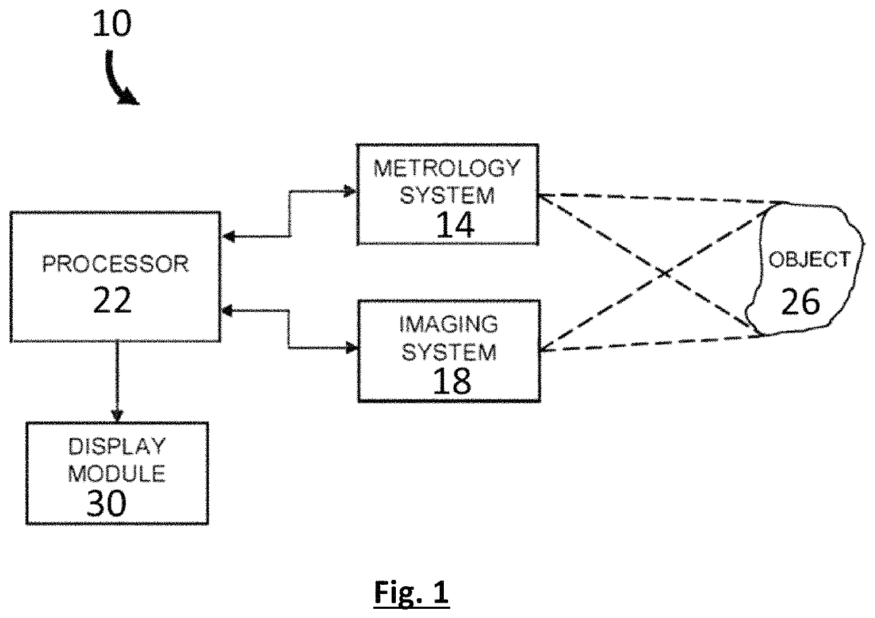
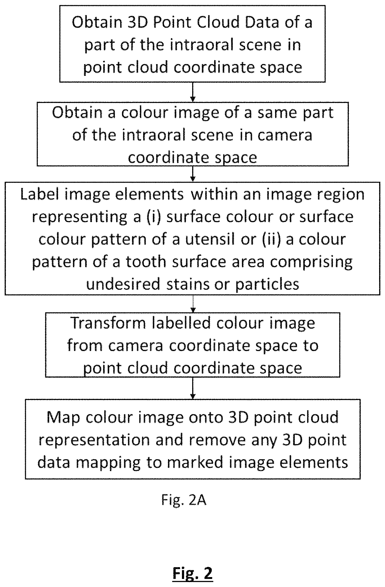
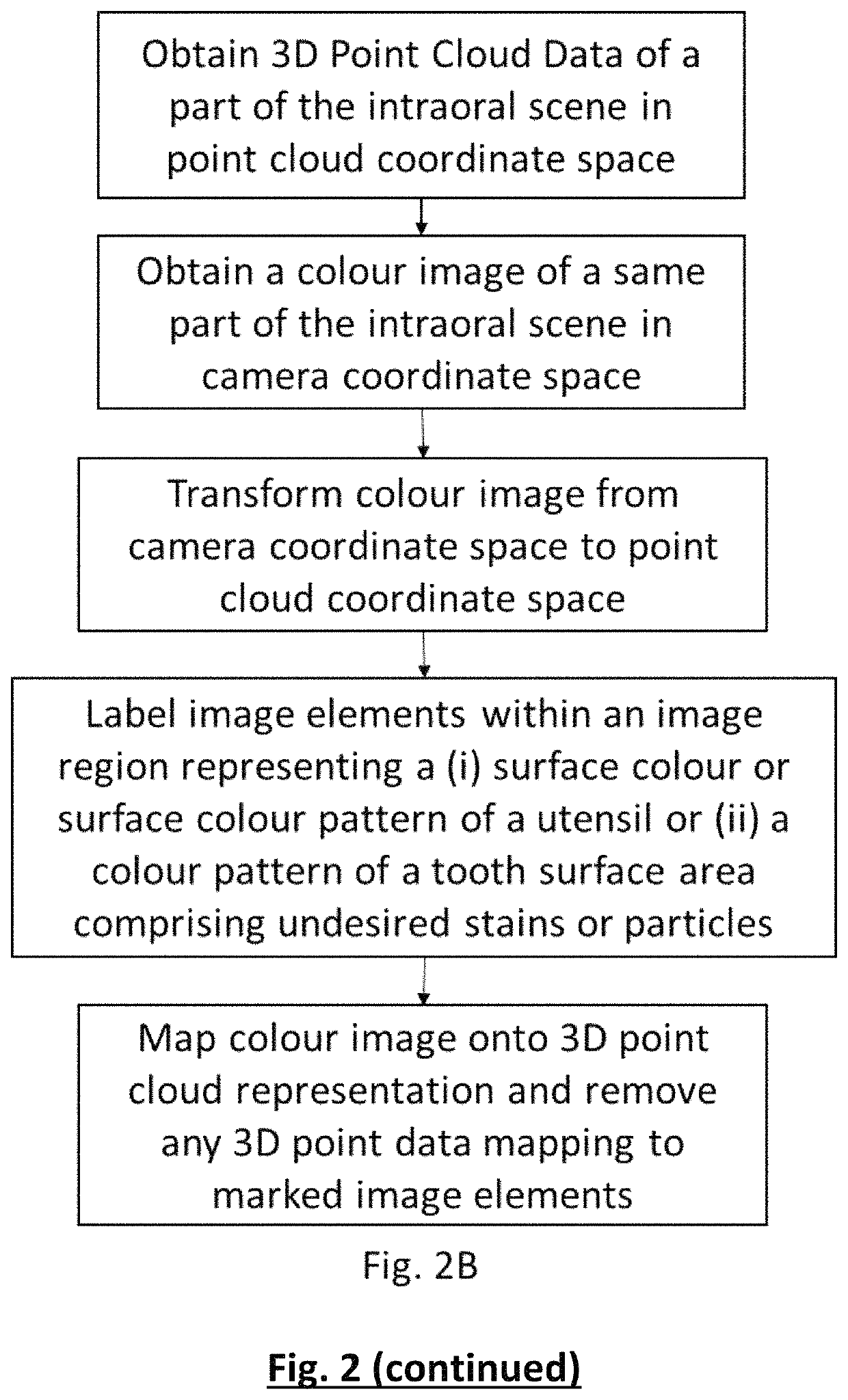
[0094]The intraoral scanning system comprises a harmonic interference fringe 3D metrology device combined with an imaging device comprising a 2D colour camera and a broadband light source mounted in a scanning wand comprising a scanning tip suitable for manoeuvring in the intraoral cavity. The wand is connected to a processing unit operationally linked to a display device. The scanning device allows for sequentially acquiring scanning datasets each comprising 3D point cloud data together with a corresponding colour image of a part of the intraoral cavity within the field of view of the scanning device. By moving the scanner tip over the intraoral scene scanning datasets comprising overlapping spatial data are obtained. The processing unit is coded to filter from the 3D point cloud data any data points data mapping onto image elements of the corresponding colour image that are labelled to represent a surface of which the incorporation in the 3D representation is unwant...
example 2
Geometrical Data from the 3D Point Cloud Data Originating from Green or Blue Utensils
[0095]The processor of an intraoral scanning system according to Example 1 is programmed to label the 2D colour image elements, which has a colour code within a range corresponding to a green and a blue shade as well as the image elements adjacent to such image elements. A colour code [PCr, PCb] of a pixel image element is considered to be within the range of a shade when its colour distance d from a reference shade value [RCr, RCb] is within a range from 0 to 20, wherein d=√{square root over ((RCr−PCr)2+(RCb−PCb)2)}. In this example the reference green and blue shades are defined by the Cr Cb values [49, 101] and [83, 198], respectively.
[0096]The intraoral scanning system is used by an operator who during scanning guides tongue and check tissue with a green gloved finger. The 2D view on the display device indicates that the green fingertip frequently appears within the field of view of the scanning...
example 3
Geometrical Data from the 3D Point Cloud Data Originating from a Utensil Having Surface Colour Pattern
[0098]The processor of an intraoral scanning system according to Example 1 is programmed to label the image elements within a region comprising a blue and green pattern and to filter from the 3D point cloud data any data points that mapped to the labelled image elements of a corresponding colour image. Examples of possible utensil colour patterns are represented in FIG. 6.
[0099]The labelling of the image elements is performed as indicated in the flow chart of FIG. 5. Connected colour image elements having a colour code within a range corresponding to a green (colour0) and a blue shade (colour1) are identified. A colour code [PCr, PCb] of a pixel image element is considered to be within the range of a shade when its colour distance d from a reference shade value [RCr, RCb] is within a range from 0 to 20, wherein d=√{square root over ((RCr−PCr)2+(RCb−PCb)2)}. In this example the refer...
PUM
 Abstract
Description
Claims
Application Information
 - R&D
- Intellectual Property
- Life Sciences
- Materials
- Tech Scout
- Unparalleled Data Quality
- Higher Quality Content
- 60% Fewer Hallucinations
Browse by: Latest US Patents, China's latest patents, Technical Efficacy Thesaurus, Application Domain, Technology Topic, Popular Technical Reports.
© 2025 PatSnap. All rights reserved.Legal|Privacy policy|Modern Slavery Act Transparency Statement|Sitemap|About US| Contact US: help@patsnap.com


