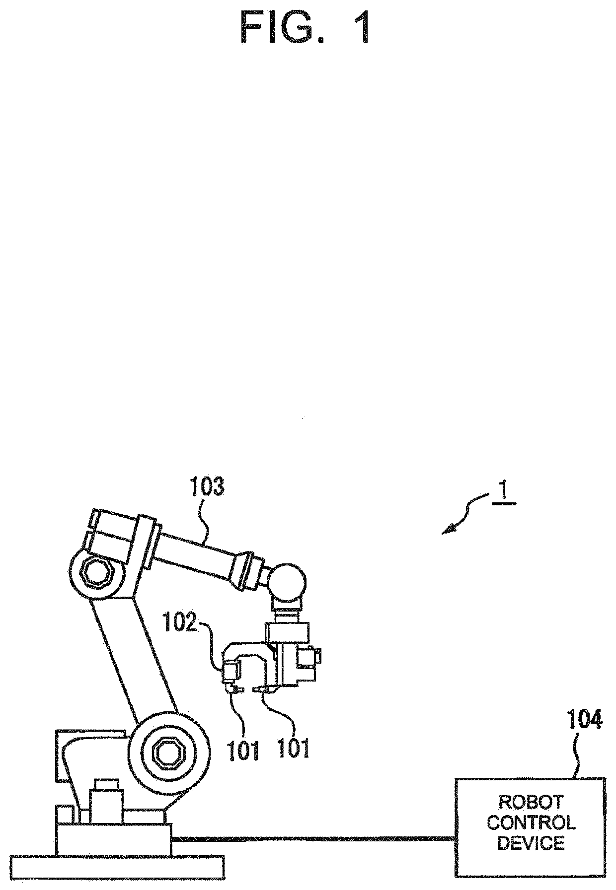
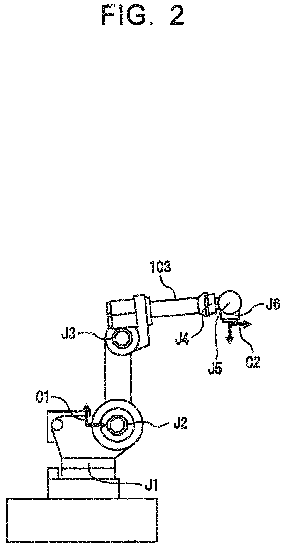
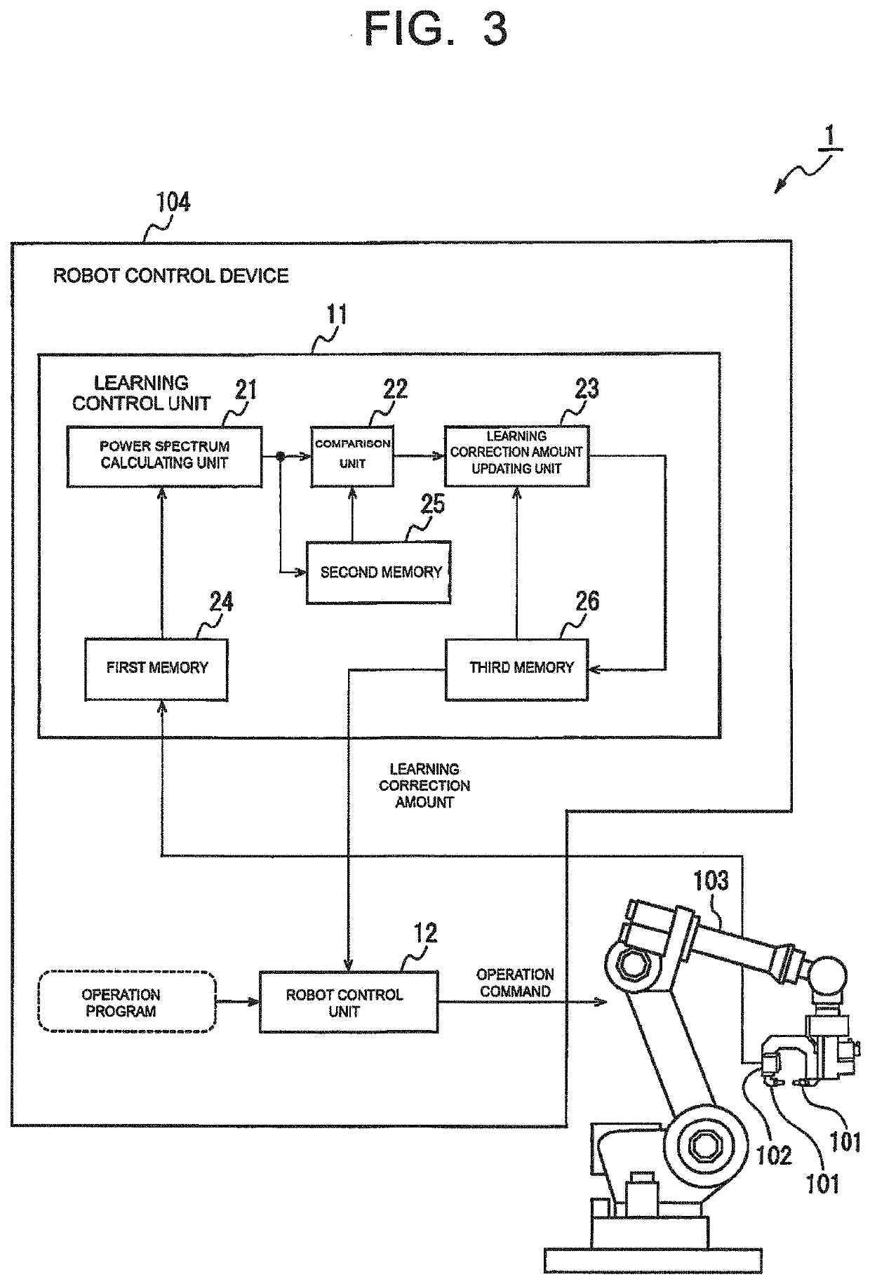
Robot system configured to perform learning control
a learning controller and robot technology, applied in the field of robot systems, can solve the problems of difficult to actually acquire frequency response data, delay in phase in the learning controller, and time and effort required to measure frequency response, so as to reduce vibration and increase gain, the effect of reducing vibration
- Summary
- Abstract
- Description
- Claims
- Application Information
AI Technical Summary
Benefits of technology
Problems solved by technology
Method used
Image
Examples
first embodiment
[0062]The learning control by the learning correction amount updating unit 23 described above can be schematically represented as Equation 1 below in a case that it is expressed by an equation. In Equation 1, ui represents the learning correction amount for the i-th learning (i is an integer), ei represents the vibration of the control target portion 101 for the i-th learning, the function Fp represents the application of a filter configured to advance the phase by the phase advance amount, the function Q represents the application of a low-pass filter configured to define the control band of the learning control unit 11, and the function L represents the application of the learning control, respectively.
ui+1=Q(Fpui+LFpei) (1)
[0063]FIG. 13 is a Bode diagram showing an example of the frequency characteristics of a filter in a learning correction amount updating unit according to the first embodiment. For example, at the time of the current learning (i-th time), it is assumed that ...
second embodiment
[0069]The learning correction amount updating process by the learning correction amount updating unit 23 according to the above-described second embodiment is represented by Equation 2 below. In Equation 2, W(ω) represents a weighting function for advancing the phase of a specific frequency component in the frequency domain. Assuming that the phase advance amount calculated by the phase advance amount calculating unit 31 is θ, the frequency component whose phase should be advanced is multiplied by eiθ, and the frequency component whose phase need not be advanced is multiplied by 1.
FOURIER TRANSFORM PHASE ADJUSTMENT INVERSE FOURIER TRANSFORM
[0070]f(t)→F(ω)→F(ω)W(ω)→f′(t)W(ω)={1(ω∈Ω)|eiθ(ω∈Ω)(2)
[0071]In Equation 2, the learning correction amount f (t) used for correcting the operation command at the time of the current learning in the time domain is Fourier-transformed by the Fourier transform unit 33. The learning correction amount used for correcting the operation command at the tim...
third embodiment
[0072]FIG. 15 is a block diagram illustrating a learning control unit including a learning correction amount updating unit according to a
[0073]In the first and second embodiments, the phase is advanced only for a specific frequency component (i.e., the frequency component of the learning correction amount corresponding to the frequency component at the time of the current learning, the frequency component having a power spectrum greater than the power spectrum at the time of the immediately preceding learning) among the frequency components of the learning correction amount, so that the power spectrum for all frequency components at the time of the current learning are intended to become less than the power spectrum at the time of the immediately preceding learning. On the other hand, in the third embodiment, not for a specific frequency component among the frequency components of the learning correction amount but the entire learning correction amount (i.e., for all frequency compo...
PUM
 Abstract
Description
Claims
Application Information
 - R&D
- Intellectual Property
- Life Sciences
- Materials
- Tech Scout
- Unparalleled Data Quality
- Higher Quality Content
- 60% Fewer Hallucinations
Browse by: Latest US Patents, China's latest patents, Technical Efficacy Thesaurus, Application Domain, Technology Topic, Popular Technical Reports.
© 2025 PatSnap. All rights reserved.Legal|Privacy policy|Modern Slavery Act Transparency Statement|Sitemap|About US| Contact US: help@patsnap.com


