
Protective barrier for a control panel

a technology for protecting barriers and control panels, applied in mechanical control devices, lifting devices, dashboard fitting arrangements, etc., can solve problems such as involuntary movement of mweps, affecting the safety of operators on the work platform and at ground level, and reducing the number of contact points between operators and machines, reducing the risk of operator receiving electric shocks, and increasing electrical resistance

Inactive Publication Date: 2020-06-11
CONTROL SHELL LTD
View PDF0 Cites 1 Cited by
  • Summary
  • Abstract
  • Description
  • Claims
  • Application Information

AI Technical Summary

Benefits of technology

The patent describes a protective barrier made from a silicone elastomer that was found to be effective in preventing moisture and deformation during use. Silicone elastomers are also less susceptible to aging factors and can absorb vibrations to minimize the effects on the operator's body. These barriers are ideal for protecting control panels of MEWPS that are exposed to ozone, UV, and heat while in use.

Problems solved by technology

A known disadvantage of conventional MWEPs is that their control panels are susceptible to moisture ingress which is the most common cause of MWEP downtime.
Further, moisture ingress to control circuits is also known to cause involuntary movement in MWEPs which is hazardous to both operators on the work platform and at ground level.
While efforts have been made to prevent the ingress of moisture into control panels, for instance by spraying control panels with aerosol sprays that contain a blend of waxes and oils, the thin films that are formed are not robust and can easily be washed away.
A further disadvantage of such thin films is that they offer little in the way of impact resistance, meaning that there is an increased risk that falling objects, e.g. branches from a tree or debris from a building site, could damage the control panel, leading to an extended period of downtime while the control panel is repaired.

Method used


Image

  • Protective barrier for a control panel
  • Protective barrier for a control panel
  • Protective barrier for a control panel

Examples


Embodiment Construction

[0033]In order that the invention may be more clearly understood embodiments thereof will now be described, by way of example only, with reference to the accompanying drawings, of which:

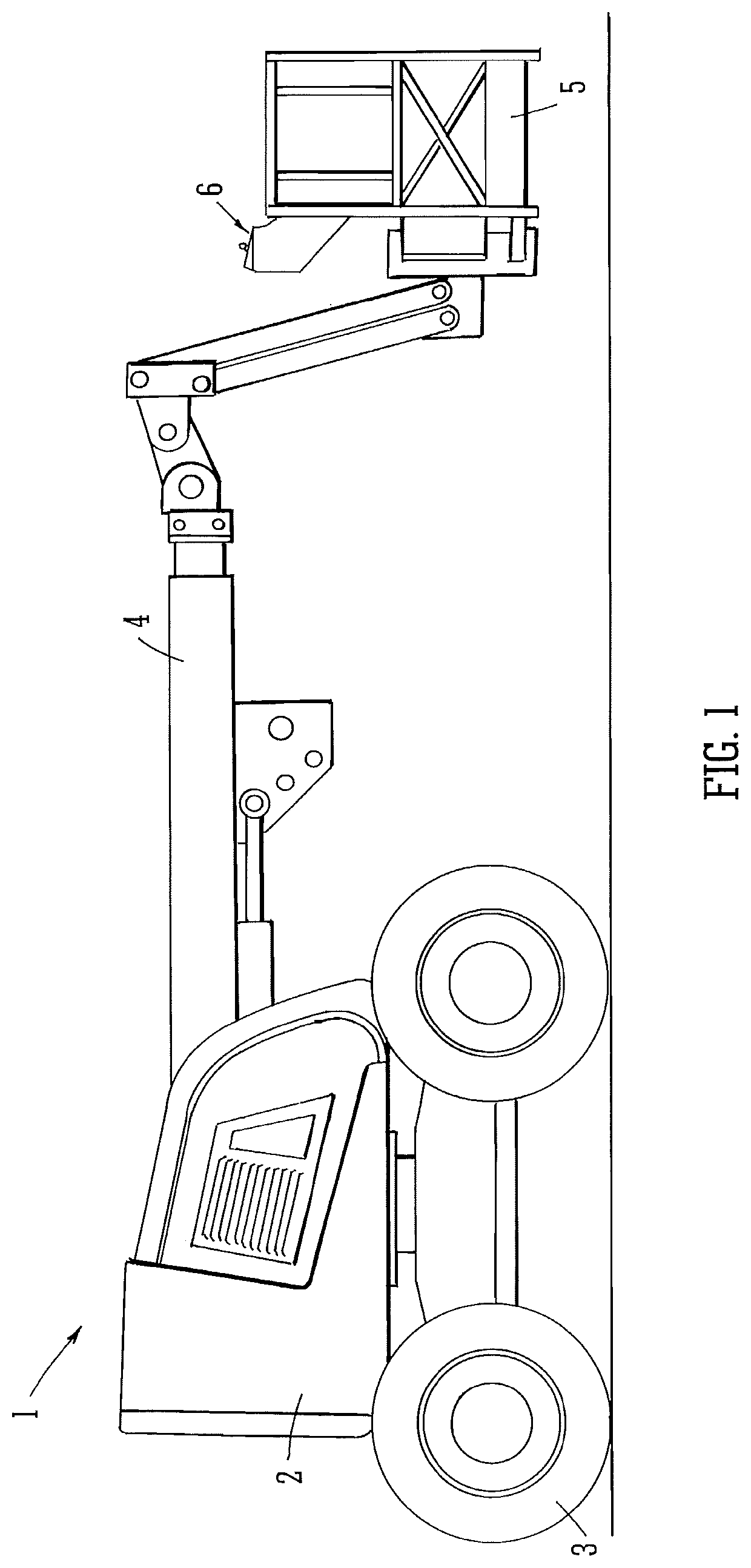
[0034]FIG. 1 shows a perspective view of a mobile elevated work platform

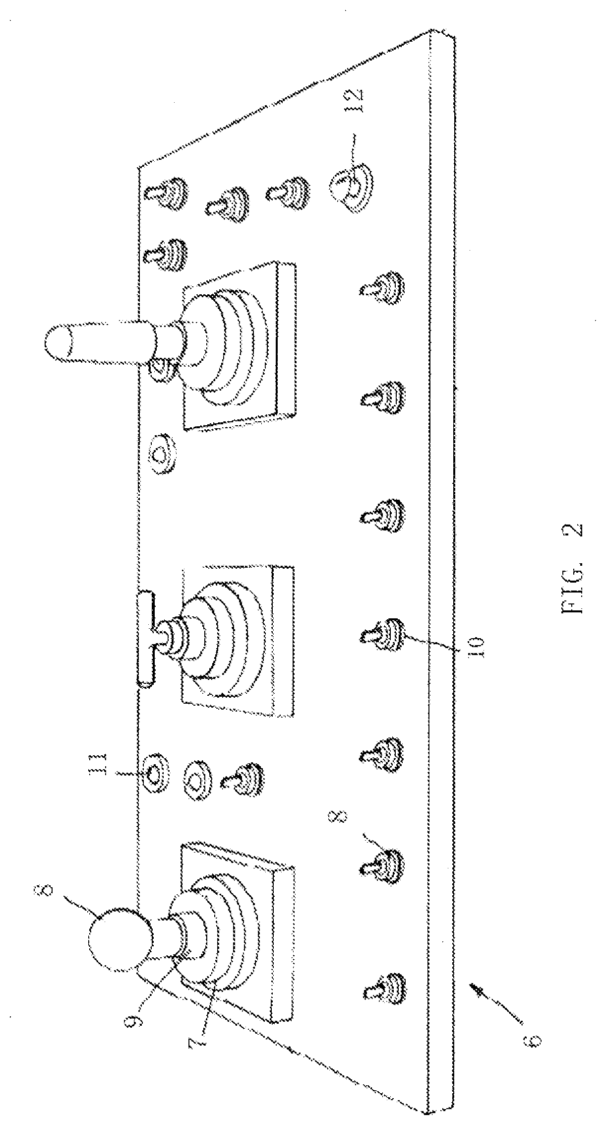
[0035]FIG. 2 shows a perspective view of a mobile elevated work platform control panel.

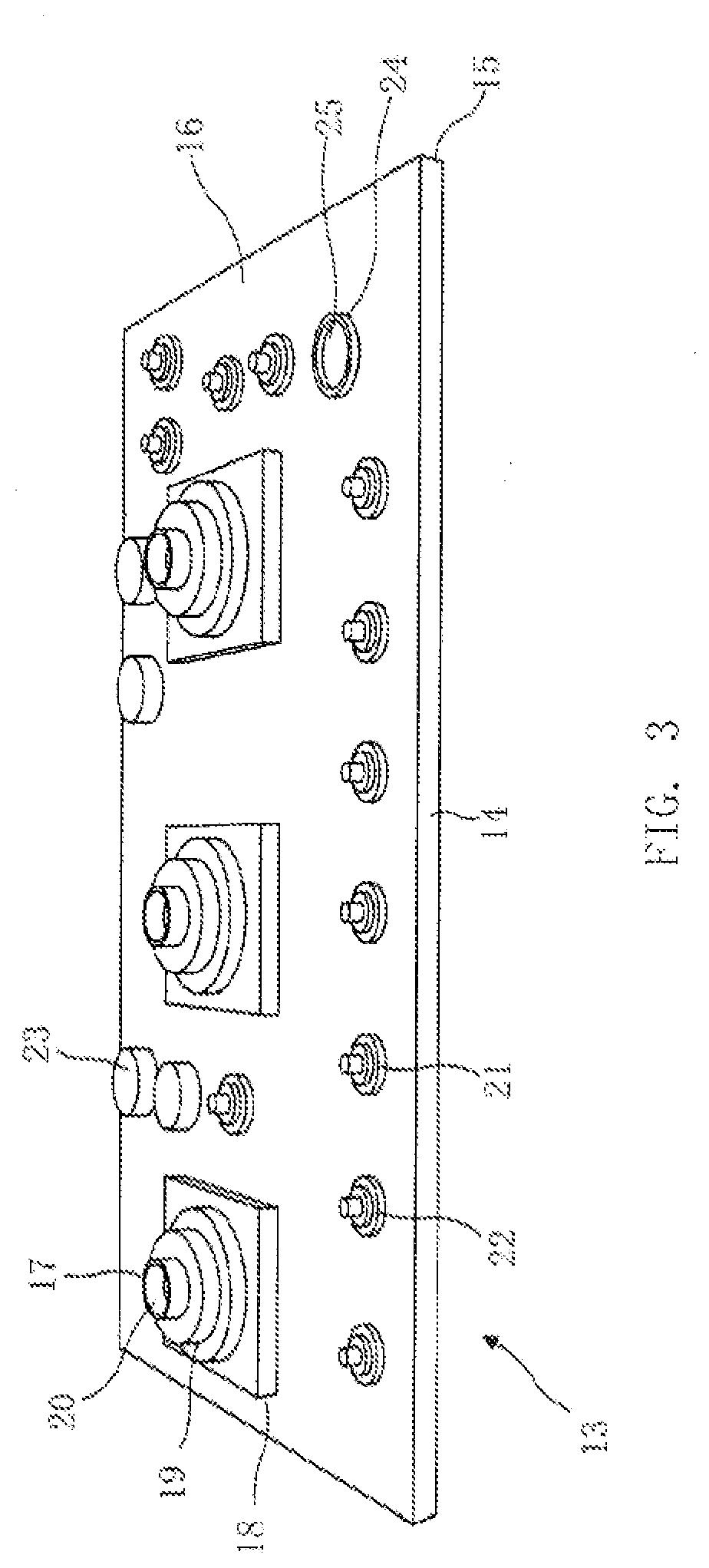
[0036]FIG. 3 shows a perspective view of a protective barrier according to the present invention.

[0037]FIG. 4 shows a cross-section of a control panel provided with a protective barrier and with a protective shell.

[0038]With reference to FIG. 1 there is shown a mobile elevated work platform (MWEP) 1. The MWEP 1 has a drivable vehicle body 2 having wheels 3 and an extendable boom 4 mounted at one end to the vehicle body 3. A basket 5 is mounted onto the free end of the boom 4 away from the vehicle body 3. The basket 5 is provided with a set of controls (not shown) in the form of a control panel 6 so that, in use, an operator standing in the bask...


PUM


Abstract

The present invention relates to a mobile elevating work platform comprising a control panel, said control panel (6) comprising a protective barrier (13) on an outer surface thereof, wherein the protective barrier comprises an elastomer. The present invention also relates to a method for providing a control panel with a protective barrier (13), which comprises the steps of obtaining a three-dimensional profile of an outer surface of a control panel, creating a mould from the three-dimensional profile, providing an elastomer and shaping the elastomer in the mould, curing the elastomer to form the protective barrier and fitting the protective barrier to the control panel. The present invention also relates to a mobile elevating work platform (MEWP) comprising a control panel (6) and a rigid shell (26) for protecting the control panel.

Description

TECHNICAL FIELD OF THE INVENTION[0001]The present invention relates to a protective barrier for a control panel, particularly a control panel of a mobile elevating work platform, and to a method for manufacturing the same.BACKGROUND TO THE INVENTION[0002]Mobile elevating work platforms (MEWPs), also known as aerial work platforms (AWPs) are mechanical devices that allow inaccessible areas, usually at height, to be accessed by people and / or equipment. “Cherry picker”, “scissor lift” and diesel boom devices are well known examples of MEWPs and are generally used in the construction and telecommunication industries.[0003]The position of the work platform is typically controlled by an operator using a control panel. The control panel may be located on the work platform itself which enables the operator on the work platform to control the position of the work platform. Alternatively, the position of the work platform may be adjusted by an operator at ground level using a control panel lo...

Claims


Application Information

Patent Timeline
IPC IPC(8): B66F11/04B66F9/075B60K37/06H01H13/86G05G25/04
CPCB66F11/046H01H2009/048B60K2370/692H01H13/86B66F9/07504B60K37/06G05G25/04B60K35/10B60K2360/692
Inventor REYNOLDS, JOHN
Owner CONTROL SHELL LTD
Learn More