Device for measuring light exposure of a subject

a technology for light exposure and subject, applied in the field of devices for measuring light exposure of subjects, to achieve the effect of accurate and realistic light measurement, high total effectivity, and efficient collection of ligh

Inactive Publication Date: 2020-06-11
LYS TECH LTD
View PDF0 Cites 3 Cited by
  • Summary
  • Abstract
  • Description
  • Claims
  • Application Information

AI Technical Summary

Benefits of technology

[0012]Measuring and quantifying the light exposure of a subject during the day and night is useful for alleviating the problems mentioned earlier, such as sleep disruption and low mood and energy. Such measurements preferably indicate at which times during the day the subject is exposed to the right and wrong kinds of light. Preferably, the measurements indicate the levels of blue light exposure during the day and night. Thereby, the measurements may show if the subject is exposed to too low intensity of light during the day or excessive amounts of light in the evening shortly before going to sleep. Avoiding such light patterns will lead to improved health and increases the well-being of the subject.
[0014]The ganglion cells are present in a large part of the retina, and are therefore also exposed to light coming from a wide range of directions. The device should therefore preferably gather light from many directions for the measurements such that it resembles the way the light affects the retinal ganglion cells in the eyes. Thereby the device gives an accurate and realistic measure of the light that the eyes are exposed to during the day. Therefore, in one embodiment the device is constructed such that the light guide is configured for collecting light from substantially all directions within a hemisphere with respect to the device and direct said light to the light sensor. In one example, the device could be attached to the clothes of the subject and pointing forwards in the same direction as the subject would normally be looking. The light guide may then gather light from directions in a hemisphere in front of the subject and guide it towards the light sensor such that it resembles the light gathered by the eyes. Furthermore, the device should preferably gather the light efficiently such that the light guide and sensor provide a high total effectivity.
[0015]The ganglion cells in the eyes are more sensitive to light coming from the upper part of the vision, normally corresponding to light from above the horizon. Therefore, in another embodiment the light guide is configured for collecting light from primarily one quadrant, e.g. defined by a polar angle in the range between −90° and 90° and an azimuth angle in the range between 0° and 90°, and direct said light to the light sensor. In yet another embodiment the light guide is configured for collecting light from polar angles in the range between −60° and 60° and azimuth angles in the range between 0° and 60°, and direct said light to the light sensor. In another example, the device is again attached to the clothes of a subject and may be configured for gathering light from a quadrant in front of the subject and above the horizon. This may yield a more accurate measurement of the amount of light that the ganglion light cells are exposed to during the day.
[0016]The device is preferably wearable, such that it can be attached to the body, such as a bracelet, necklace or glasses, or it may be attached to the clothes by using a clip or pin. This provides an advantageous position for taking measurements of the light exposure of the subject wearing the device.
[0017]Another embodiment of the present invention relates to a wearable device for estimating the light conditions of a subject wearing the device. The device comprises a top surface, a light sensor located below the top surface for measuring said light conditions, and a light guide for collecting incoming light and directing it to said light sensor. Preferably the light guide protrudes through the top surface of the device such that it can collect light more efficiently. The light guide preferably comprises at least a transparent piece of material with a light collecting region located on the top surface of the transparent piece of material. The light collecting region is in one embodiment located above the light sensor such that light may be more efficiently directed to the sensor. The light collecting region is in one embodiment shaped like a polygon such as a triangle, square, pentagon or hexagon. In another embodiment the light collecting region is circular. The light collecting region is preferably shaped such that it efficiently directs incident light to the light sensor. Furthermore, the light collecting region is preferably shaped such that light from a wide range of directions is gathered and collected by the light collecting region and directed to the light guide. The region should gather light from a wide range of directions in order to more accurately mimic the light gathering of the human eye such that the light conditions of the subject are estimated more accurately. The top surface of the device is preferably oriented vertically when worn by the subject and such that the surface normal points straight ahead from the subject when the device is worn by the subject. The light guide is preferably configured for collecting a substantial part of the light incident on the light guide from polar angles between −90° and 90° and azimuthal angles between −90° and 90°. In another embodiment the light guide is configured for collecting a substantial part of the light incident on the light guide from polar angles between −60° and 60° and azimuthal angles between −60° and 60°, or from polar angles between −40° and 40° and azimuthal angles between −40° and 40°, or from polar angles between −30° and 30° and azimuthal angles between −30° and 30°. A substantial part of the light may here refer to at least 20%, or at least 30%, or at least 40%, or at least 50%, or at least 60%, or at least 80% of the light incident on the light guide within the specified range of directions. The light measured may be in the visible range, i.e. 400-700 nm wavelength, or it may additionally extend into the ultraviolet and / or infrared range.

Problems solved by technology

Thereby, the measurements may show if the subject is exposed to too low intensity of light during the day or excessive amounts of light in the evening shortly before going to sleep.

Method used


Image

  • Device for measuring light exposure of a subject
  • Device for measuring light exposure of a subject
  • Device for measuring light exposure of a subject

Examples


Embodiment Construction

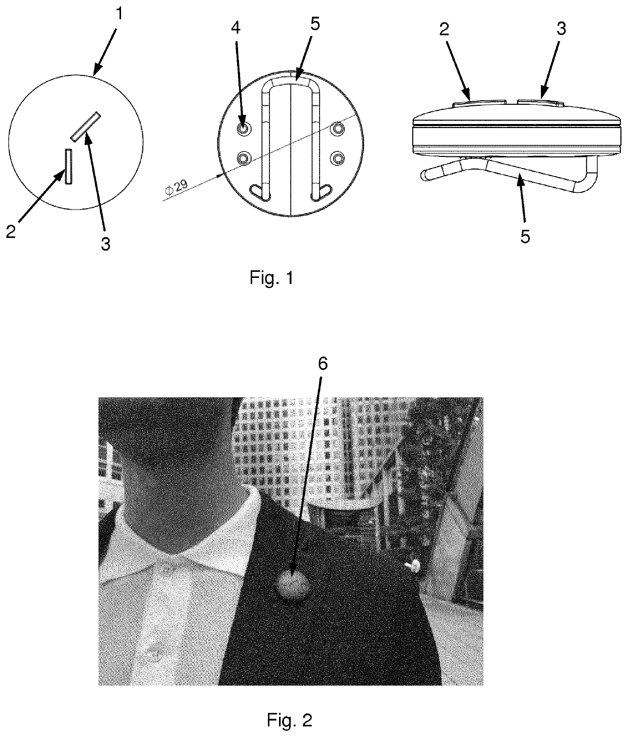
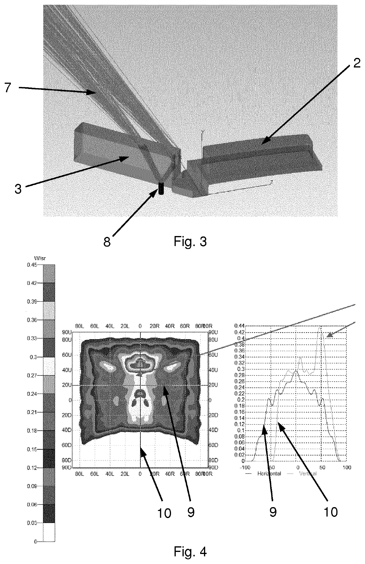
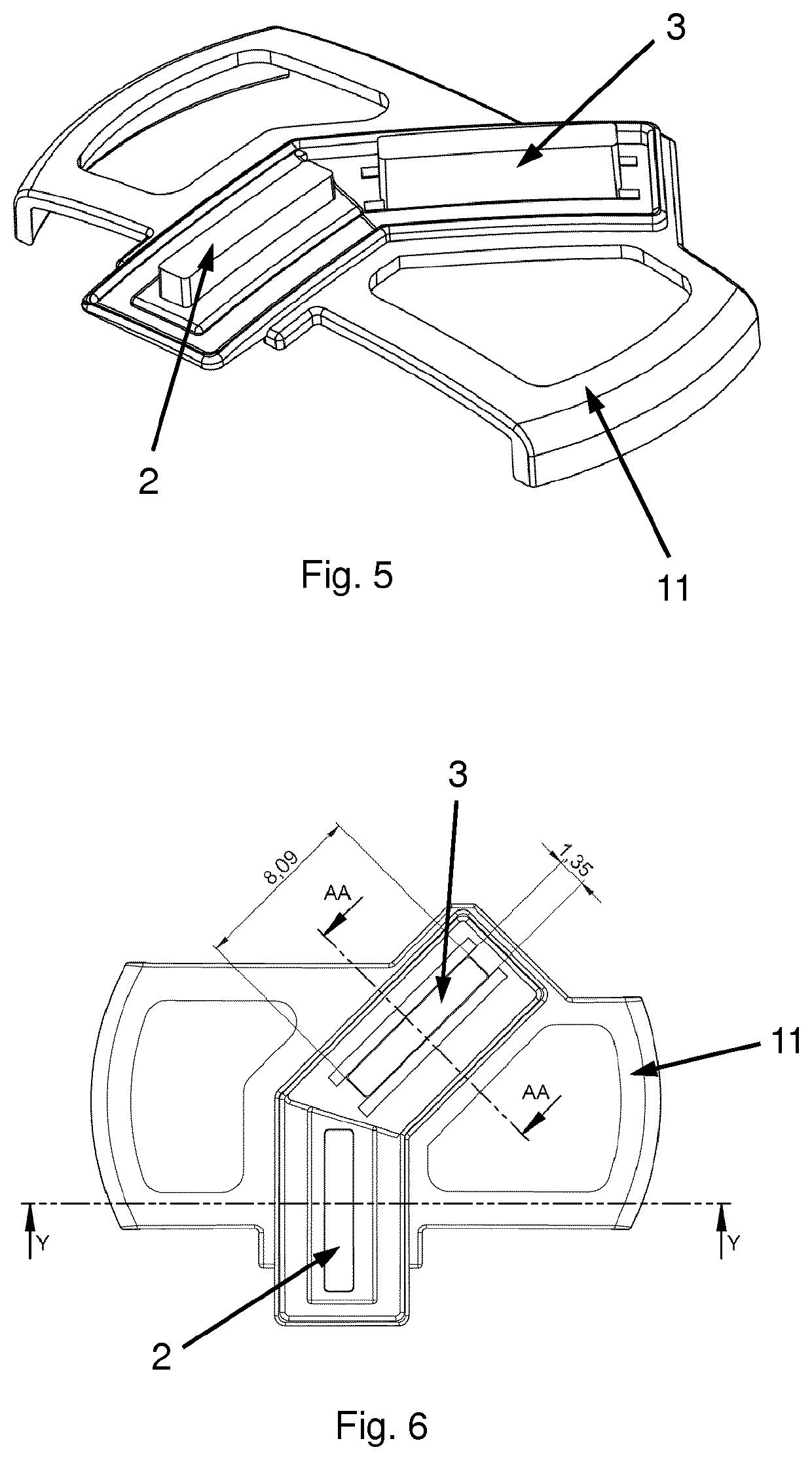
[0028]The present disclosure relates to a wearable device for collecting and measuring the light exposure of a subject. A first aspect of the invention is constructed such that a light guide gathers incoming light and guides it to a light sensor. The light guide may have a wide variety of shapes for directing the light to the sensor. The device is preferably constructed such that the peak sensitivity of the device is in the correct direction and such that the light is gathered efficiently. In one embodiment, this is achieved by having at least part of the outer surface of the light guide exposed to incoming light in the shape of a sphere or part of a sphere, such as a hemisphere. The shape of the outer surface of the light guide may also be ellipsoidal, or form part of an ellipsoid, or it could be a polyhedron, or part of a polyhedron. Other shapes that may be suitable for the outer surface of the light guide include planar, paraboloidal, cylindrical, conical, cosine shape, a plural...


PUM


Abstract

A wearable device for measuring the light conditions of a subject includes a light sensor for measuring said light conditions, and a light guide for collecting incoming light and directing it to said light sensor. A software application is also provided executable on a remote device and configured for receiving data from the wearable device via a receiver on the remote device, processing the data by means of the remote device to provide data representing the light exposure of the subject wearing the wearable device, and displaying at least a part of the data on a screen of the remote device.

Description

[0001]The present invention relates to a wearable device for measuring and managing the light conditions of a subject.BACKGROUND OF INVENTION[0002]Life is dependent on circadian rhythms to ensure the best use of daylight hours and to promote rest in the darkness, which promotes repairing and renewing of cells and during which memory adjustments can be carried out for the next day.[0003]On an overcast day in Europe, the intensity of natural light is around 10,000 lux, and may be as high as 100,000 lux on bright sunny days. Yet homes and work in offices, factories, schools and hospitals are often isolated from natural light and the artificial light in these places is often around 200 lux and seldom exceeds 400-500 lux[0004]Light is the main reference of time for the circadian system and the eye is the only source of light information for our brain. The problem is that we grab light and we then forget that we received it, because the eye needs to form the vision. We therefore don't hav...

Claims


Application Information

Patent Timeline
Patent Type & Authority Applications(United States)
IPC IPC(8): G01J1/02G01J1/04G01J1/32
CPCG01J1/32G01J1/0219G01J1/0266G01J1/0233G01J1/0403G01J1/0422G01J1/0242G01J1/0247G01J1/0407G01J1/0411G01J1/0477G01J1/0488G01J1/4204G01J3/0205G01J3/0208G01J3/0216G01J3/0264G01J3/0272G01J3/0289G01J3/465G01J2001/0257G01J2001/0261G01J2001/4266
Inventor PETERSEN, CHRISTINA CATHARINA FRIIS BLACH
Owner LYS TECH LTD
Why Eureka
Try Eureka