Apparatus and method for measuring a capacitance, and a fingerprint sensor utilizing the same

Active Publication Date: 2020-06-11
NXP BV
View PDF0 Cites 2 Cited by
  • Summary
  • Abstract
  • Description
  • Claims
  • Application Information

AI Technical Summary

Benefits of technology

[0025]More specifically, the first sub-plate may be formed by a plurality of first sub-sub-plates which are physically separated both electrically interconnected, e.g. by wiring. Similarly, the second sub-plate may be formed by a plurality of second sub-sub-plates which are physically separated both electrically inte

Problems solved by technology

Integration of a capacitance measurement device into a mains-operated device may cause noise being coupled into the device and hence impact the measurement result.
Capacitance measurement devices that may e.g. measure the capacitance between parts of a human body and an array of sensing electrod

Method used


Image

  • Apparatus and method for measuring a capacitance, and a fingerprint sensor utilizing the same
  • Apparatus and method for measuring a capacitance, and a fingerprint sensor utilizing the same
  • Apparatus and method for measuring a capacitance, and a fingerprint sensor utilizing the same

Examples


Example

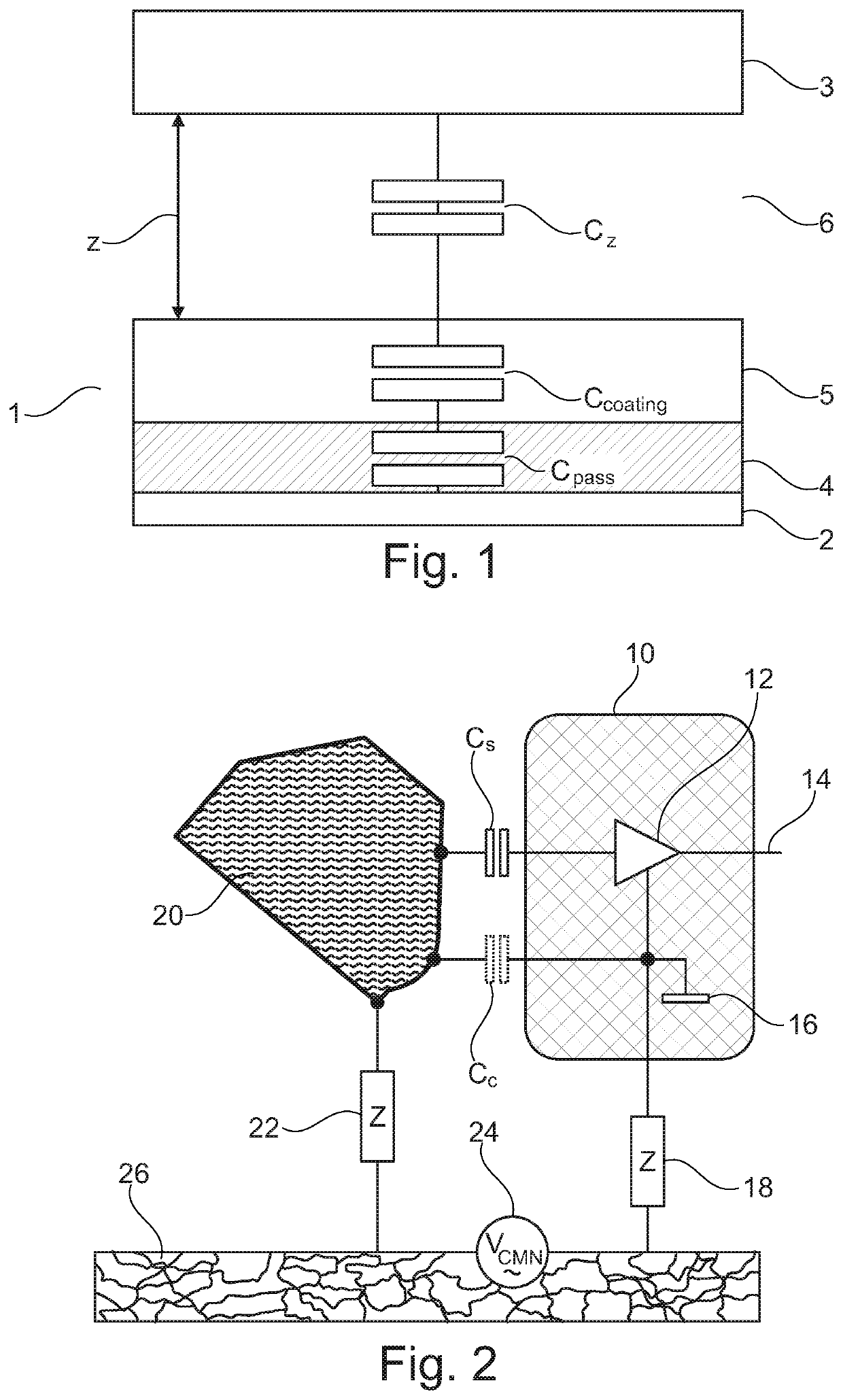
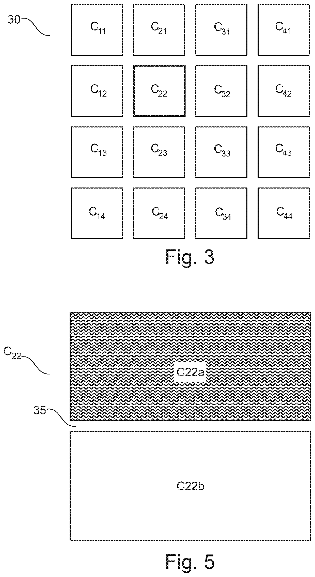
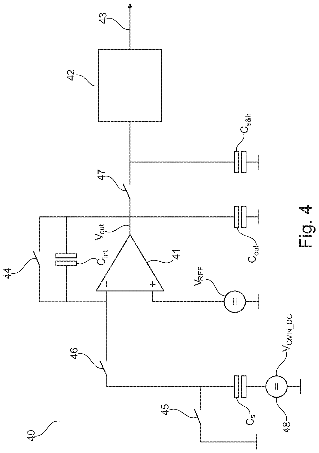
[0041]The illustration in the drawing is schematic. It is noted that in different figures, similar or identical elements are provided with the same reference signs or with reference signs, which differ only within the first digit.

[0042]FIG. 1 shows the structure of a capacitive sensor element 1. More specifically, the sensor element 1 comprises a sense plate 2 (or sense electrode) facing a counter plate 3 (which may be the surface of a conductive object, such as e.g. a user's finger) such that the sense plate 2 and the counter plate 3 form opposing plates of a capacitor. The surface of the sense plate 2 that faces the counter plate 3 is covered with a passivation layer 4 having a capacitance Cpass and a coating 5 having a capacitance Ccoating. Furthermore, an air gap 6 having a capacitance Cz is present between the coating 5 and the counter plate 3. As known in the art, the width z of the air gap 6 influences the overall capacitance of the resulting capacitor (i.e., the capacitance ...


PUM


Abstract

There is described an apparatus for measuring a capacitance formed by a sense plate and a counter plate, wherein the sense plate comprises a first sub-plate and a second sub-plate, the first sub-plate and the second sub-plate being electrically separated. The apparatus comprises (a) a first integrator comprising a first integrator input terminal, a first integrator reference terminal connected to a first reference voltage, and a first integrator output terminal for providing a first output voltage indicative of a capacitance connected to the first integrator input terminal, (b) a second integrator comprising a second integrator input terminal, a second integrator reference terminal coupled to a second reference voltage, and a second integrator output terminal for providing a second output voltage indicative of a capacitance connected to the second integrator input terminal, (c) switching circuitry adapted to, at a first measurement point in time, connect the first integrator input terminal to the first sub-plate and connect the second integrator input terminal to the second sub-plate, and, at a second measurement point in time, connect the first integrator input terminal to the second sub-plate and connect the second integrator input terminal to the first sub-plate, and (d) output circuitry coupled to the first integrator output terminal and the second integrator output terminal and adapted to generate an output signal based on a difference between the first output voltage and the second output voltage, the output signal being indicative of the capacitance formed by the sense plate and the counter plate. There is also described a fingerprint sensor and a method.

Description

FIELD OF THE INVENTION[0001]The present invention relates to the field of capacitance measurement, in particular to an apparatus and a method for measuring a capacitance formed by a sense plate and a counter plate. The present invention further relates to a fingerprint sensor utilizing the apparatus and method.ART BACKGROUND[0002]Integration of a capacitance measurement device into a mains-operated device may cause noise being coupled into the device and hence impact the measurement result. Capacitance measurement devices that may e.g. measure the capacitance between parts of a human body and an array of sensing electrodes, may exhibit performance issues caused by noise originating from switched mode power supplies or picked-up RF noise being coupled between the device's ground potential and the body potential. Such noise may modulate the bottom plate of the capacitor under test, resulting in measurement errors.[0003]Thus, there may be a need for a simple and efficient way of suppre...

Claims


Application Information

Patent Timeline
IPC IPC(8): G06K9/00
CPCG06K9/0002G01R27/2605G06V40/1306G06F3/044
Inventor SUWALD, THOMASPHADTARE, MILINDROUTRAY, DILLIP KUMAR
Owner NXP BV
Why Eureka
Try Eureka