Image processing apparatus, image processing method, and storage medium

a technology of image processing and image processing method, which is applied in the field of image processing apparatus, image processing method, and storage medium, can solve the problems of affecting the sharpness of the whole image, etc., and achieves excellent sharpness, reduces color development defects, and reduces granularity

Active Publication Date: 2020-06-11
CANON KK
View PDF0 Cites 8 Cited by
  • Summary
  • Abstract
  • Description
  • Claims
  • Application Information

AI Technical Summary

Benefits of technology

[0009]The present invention is intended to solve the above-described problem. Thus, it is an object of the present invention to provide quantization processing that can reduce colo

Problems solved by technology

WO 2002/005545, when a characteristic pattern is included in image data of a color on which the processing is performed first, interference between the image data and the threshold matrix affec

Method used


Image

  • Image processing apparatus, image processing method, and storage medium
  • Image processing apparatus, image processing method, and storage medium
  • Image processing apparatus, image processing method, and storage medium

Examples


first embodiment

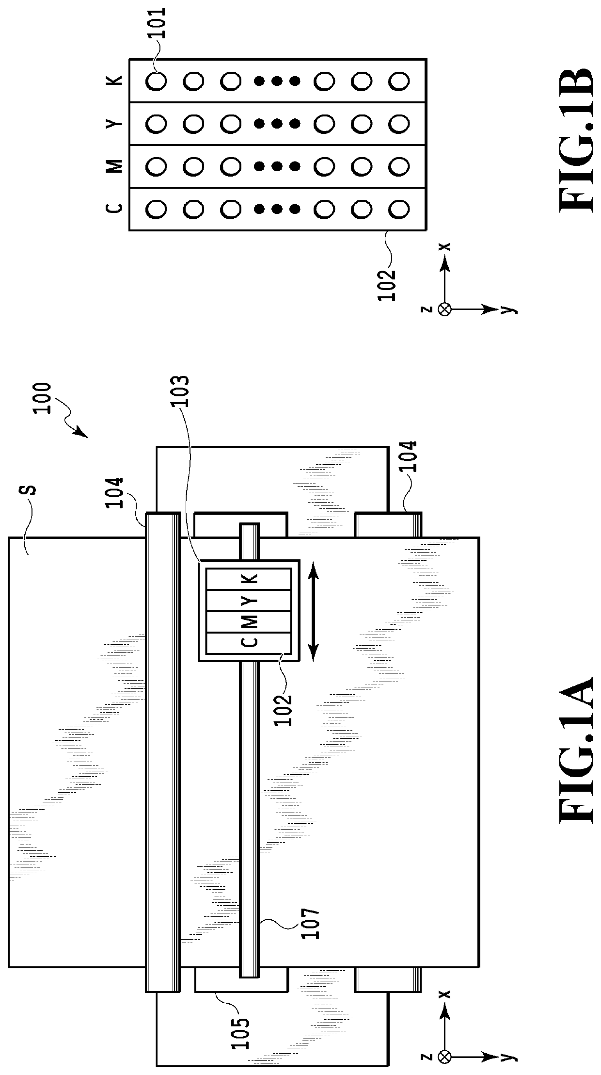
[0050]FIGS. 1A and 1B are schematic views of a printing apparatus 100 and a printing head 102 used in the present embodiment. The printing apparatus 100 used in the present embodiment is a serial ink-jet printing apparatus. In FIGS. 1A and 1B, an x direction represents the main scanning direction of the printing head, a y direction represents the conveyance direction of a print medium S, and a z direction represents the direction of ink discharge.

[0051]As illustrated in FIG. 1B, in the printing head 102, nozzle arrays configured to discharge ink of cyan (C), magenta (M), yellow (Y), and black (K), respectively, are arranged in parallel to each other in the x direction. In each nozzle array, multiple nozzles 101 configured to discharge ink in the z direction in accordance with print data are arrayed in the y direction.

[0052]As illustrated in FIG. 1A, the printing head 102 is mounted on a carriage 103, and the carriage 103 is movable in the positive and negative x directions along a c...

second embodiment

[0105]In the present embodiment as well, the quantization processing is performed in accordance with the flowchart illustrated in FIG. 5 by using the image processing apparatus described with reference to FIGS. 1 to 4. In the present embodiment, the content of the exclusion value information (accumulative dot information) is different from that in the first embodiment. In the first embodiment, the exclusion value H before update is incremented by “1” at a pixel for which dot arrangement of the processing target color is determined irrespective of an ink color as the processing target color. However, in the present embodiment, a weight coefficient wi that is different for each ink color is prepared, and the exclusion value H before update is incremented by the weight coefficient wi of the processing target color.

[0106]In the present embodiment, the weight coefficient of each ink color is set based on an optical density ratio of dots printed on a print medium. In this example, the opt...

third embodiment

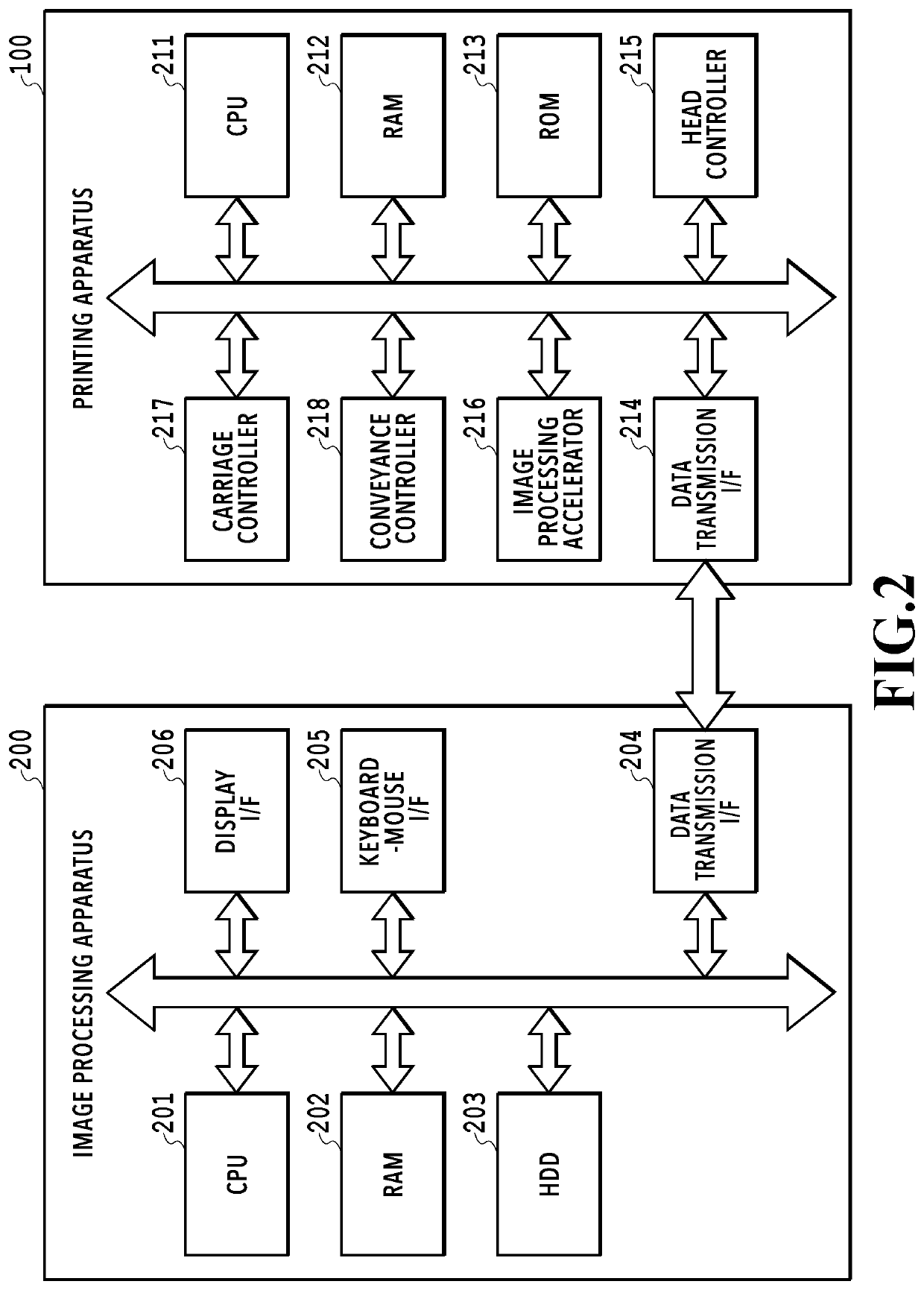
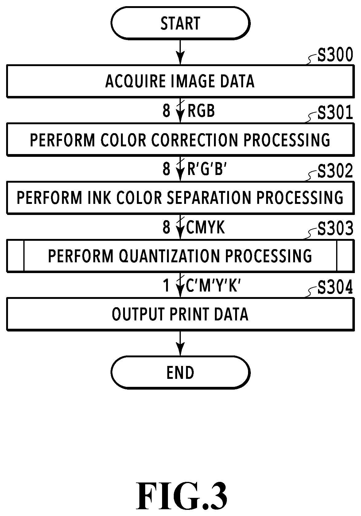
[0122]In the present embodiment as well, a series of image processing is performed in accordance with the flowchart illustrated in FIG. 3 by using the image processing apparatus described with reference to FIGS. 1 and 2.

[0123]FIG. 9 is a block diagram for description of a functional configuration in the quantization processing of the present embodiment. Differences from FIG. 4 are as follows: an evaluation value setting unit 901 uses the threshold matrix 411 as the reference value information, and a dot arrangement history information 903 is prepared in place of the accumulative dot number information 410. The dot arrangement history information 903 is information in which dot arrangement information of an ink color for which the dot arrangement data is already generated is stored in association with the ink color. The evaluation value setting unit 901 according to the present embodiment sets the evaluation value Ev for each pixel by using the threshold matrix 411 and the dot arrang...


PUM


Abstract

Provided is quantization processing that can reduce color development defect due to dot overlapping and can output an image with reduced granularity when the image is printed by using multiple kinds of colorants. To this end, dot arrangement information for a colorant for which dot arrangement is already determined among multiple kinds of colorants is acquired for a predetermined region of the image, and an evaluation value of each pixel included in the predetermined region is derived based on the arrangement information. In addition, for the predetermined region, a target value for a predetermined colorant for which dot arrangement is yet to be determined is derived based on the image. Then, whether or not to arrange a dot of the predetermined colorant in the predetermined region is determined based on the target value and the evaluation value.

Description

BACKGROUND OF THE INVENTIONField of the Invention[0001]The present invention relates to an image processing apparatus, an image processing method, and a storage medium that generate quantized data for forming an image on a print medium.Description of the Related Art[0002]A dither method is known as a quantization method for printing an image by using a pseudo gradation method. The dither method uses a dither matrix in which thresholds associated with individual pixels are arrayed, and determines whether or not to perform dot printing for each pixel by comparing the associated threshold with a pixel value indicated by image data.[0003]International Publication No. WO 2002 / 005545 discloses a dither method of using a common dither matrix for pieces of image data for multiple kinds of colorants used in a printing apparatus while correcting the dither matrix. Specifically, quantization processing on image data of a color processed first is performed by directly using thresholds stored in...

Claims


Application Information

Patent Timeline
IPC IPC(8): G06K15/02G06K15/10
CPCG06K2215/0094G06K15/1878G06K15/10H04N1/52H04N1/4051
Inventor TAKESUE, NAOYAISHIKAWA, HISASHIYAMADA, AKITOSHI
Owner CANON KK
Why Eureka
Try Eureka