Heat source device

a heat source and heat exchanger technology, applied in water heaters, stationary conduit assemblies, sustainable buildings, etc., can solve the problems of fluid to be heated flowing in the heat exchanger being overheated, local heating is likely to occur, and fluid to be heated is likely to be boiling or denaturing. to achieve the effect of preventing local heating

Active Publication Date: 2020-06-18
RINNAI CORP
View PDF0 Cites 1 Cited by
  • Summary
  • Abstract
  • Description
  • Claims
  • Application Information

AI Technical Summary

Benefits of technology

[0005]The present invention has been made to solve the problem described above, and an object of the present invention is to provide a heat source device capable of preventing local heating.

Problems solved by technology

When the heat exchanger is heated to the high temperature while the flow rate of the fluid to be heated supplied to the heat exchanger is small, the fluid to be heated flowing in the heat exchanger is overheated and local heating is likely to occur.
As a result, there are problems that boiling or denaturation of the fluid to be heated occurs and noise due to boiling noise occurs.

Method used


Image

  • Heat source device
  • Heat source device
  • Heat source device

Examples


first embodiment

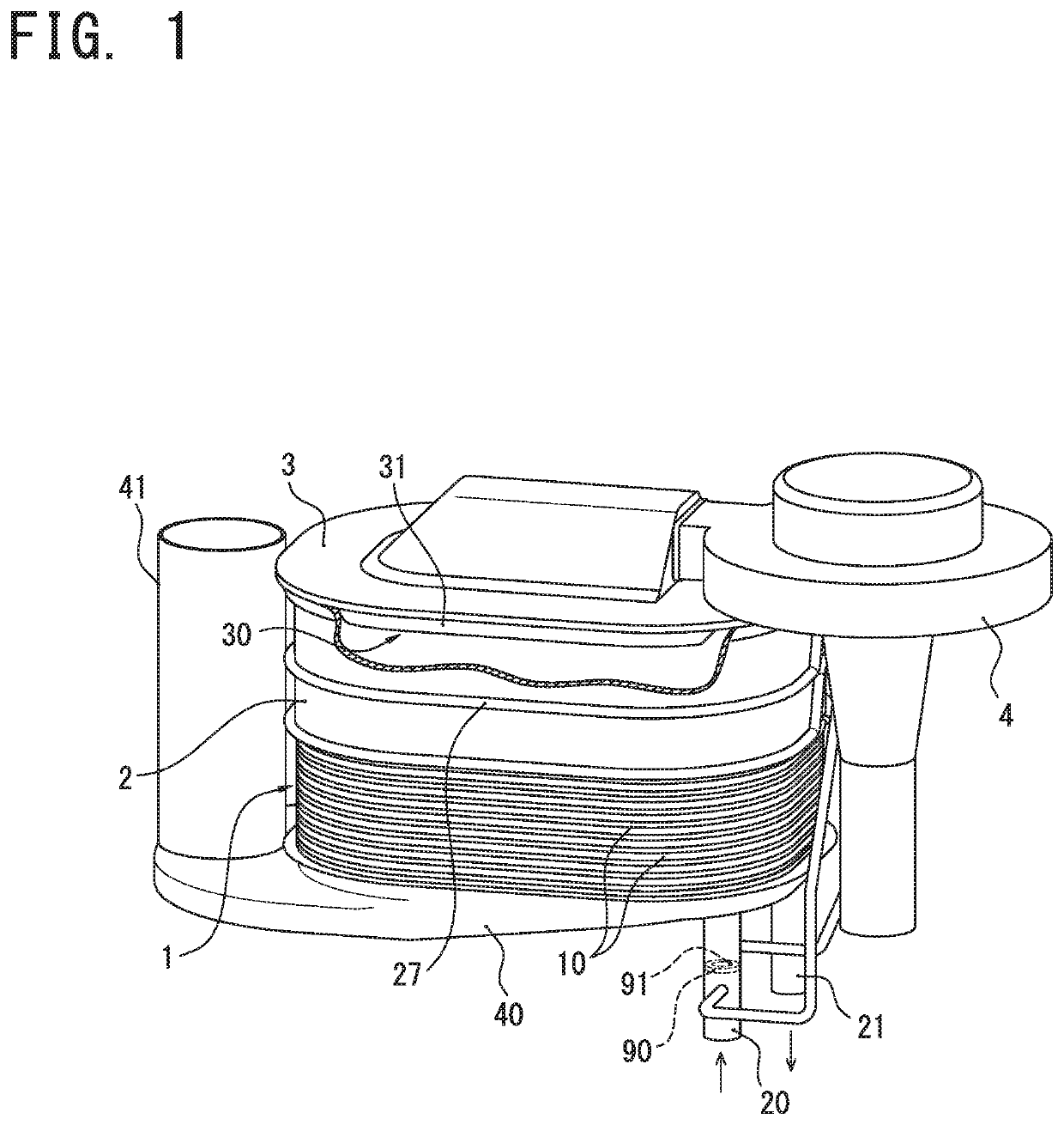
[0023]Hereinafter, referring to drawings, a heat source device according to an embodiment of the present invention will be described in detail. As illustrated in FIG. 1, a heat source device according to the present embodiment is a water heater that heats water (a fluid to be heated) flowing into a heat exchanger 1 from an inlet pipe 20 by combustion exhaust gas generated by a burner 31, and supplies the heated water to a hot water supplying terminal (not illustrated) such as a faucet or a shower through an outlet pipe 21. Although not shown, the water heater is accommodated in an outer casing. Other heating medium (for example, an antifreezing fluid) as the fluid to be heated may be used.

[0024]In this water heater, a burner body 3 constituting an outer shell of the burner 31, a combustion chamber 2, the heat exchanger 1, and a drain receiver 40 are disposed in order from the top. Additionally, a fan case 4 housing a combustion fan for feeding a mixture gas of fuel gas and air into ...

second embodiment

[0046]A heat source device according to the present embodiment has the same configuration as the first embodiment, except that an orifice plate 90 is disposed in an outlet pipe 20, and that upstream and downstream ends of a winding pipe 27 are connected to an outlet pipe 21. Therefore, common elements are assigned the same reference numerals, and their explanations are omitted.

[0047]FIG. 6 is a schematic perspective view showing the heat source device according to the present embodiment. As illustrated in FIG. 6, according to the present embodiment, the orifice plate 90 is disposed in the outlet pipe 21, so that an orifice 91 for throttling a fluid flow path for water is formed in the outlet pipe 21. Further, an upstream branch hole (upstream branch) 92 is opened on a pipe wall of the outlet pipe 21 on an upstream side of the fluid flow path for water more than the orifice 91, and the upstream end of the winding pipe 27 is connected to the upstream branch hole 92. Further, a downstr...


PUM


Abstract

A heat source device comprising: a combustion chamber (2) provided between a burner (31) and a heat exchanger (1); an inlet pipe (20) for allowing a fluid to be heated to flow in the heat exchanger (1); an outlet pipe (21) for allowing the fluid to be heated to flow out from the heat exchanger (1); and a winding pipe (27) wound around an outer surface of a peripheral wall of the combustion chamber (2), wherein either the inlet pipe (20) or the outlet pipe (21) has an orifice (91) for throttling a fluid flow path of the fluid to be heated flowing in the inlet pipe (20) or the outlet pipe (21).

Description

FIELD OF THE INVENTION[0001]The present invention relates to a heat source device configured to supply combustion exhaust gas generated by a burner to a heat exchanger through a combustion chamber. Especially, the present invention relates to the heat source device having a winding pipe wound around an outer surface of a peripheral wall of the combustion chamber.DESCRIPTION OF THE RELATED ART[0002]Conventionally, a heat exchanger including a stacked body formed by stacking a plurality of heat exchange units in which an upper heat exchange plate and a lower heat exchange plate are joined has been proposed (for example, Korean Patent No. 10-1608149 B). Each of the heat exchange units has an internal space through which a fluid to be heated flows between the upper heat exchange plate and the lower heat exchange plate, and a plurality of gas vents penetrating the internal space in a non-communicating state and through which combustion exhaust gas from a burner passes in a vertical direc...

Claims


Application Information

Patent Timeline
Patent Type & Authority Applications(United States)
IPC IPC(8): F24H8/00F24H9/18
CPCF24H1/32F24H1/445F28D2021/0024F24H8/00F24H1/34F28D9/0043F24H1/145F24H9/1836F24H1/22F24H9/0005F28D9/005F28F3/086F28D1/06F28D9/0093F28F3/12Y02B30/00F24H1/40F24H9/0015F24H9/16
Inventor ONO, TAKAHIROOJIRO, TAKASHI
Owner RINNAI CORP
Why Eureka
Try Eureka