Artificial ankle joint talus component

a technology of talus and component, which is applied in the field of artificial ankle joint talus component, can solve the problems of increasing the burden on the surgeon, osteolysis or heterotopic ossification, and the resected surface of the talus cannot be fully covered, so as to facilitate revision arthroplasty, and prevent osteolysis and heterotopic ossification

Pending Publication Date: 2020-06-25
CORENTEC +2
View PDF1 Cites 2 Cited by
  • Summary
  • Abstract
  • Description
  • Claims
  • Application Information

AI Technical Summary

Benefits of technology

[0020]The present disclosure has been made to solve the above problems, and an objective thereof is to provide an implant that conforms to the anatomical shape of a bone, thereby preventing heterotopic ossification after surgery and distributing stress.
[0021]In addition, another objective of the present disclosure is to provide an implant that conforms to the anatomical shape of the talus, thereby preventing heterotopic ossification after surgery and distributing stress.
[0022]In addition, another objective of the present disclosure is to provide an implant capable of stably guiding an insert and preventing luxation thereof.

Problems solved by technology

Clinic trials for artificial ankle joint arthroplasty, which started in the 1970s did not meet expectations because many complications occurred in early stages, and were found to increase the burden on the surgeon because the surgery procedure was highly complicated.
However, since the boundary of the anterior and the posterior is recessed inwards and is thus concave, the resected surface of the talus cannot be fully covered.
Therefore, a cross-section of the talus may be exposed in the boundary of the contact surface, and the exposed resected surface may be consistently stimulated by joint liquid, thereby causing osteolysis or heterotopic ossification, in which unnecessary bone is produced.
In addition, osteolysis causes dissociation between a bone and a prosthesis, thereby adversely affecting the lifespan of the artificial joint and, in severe cases, leading to fractures of bone surrounding the artificial joint.
If heterotopic ossification occurs after artificial ankle joint arthroplasty, a bone grows around the implant, causing joint pain and restricting joint motion, which may lead to loss of function of the artificial joint.
In particular, recent research results have reported that heterotopic ossification is accompanied by symptoms in about 5% of patients, thereby limiting the range of motion of a joint and causing severe pain in the joints, so that the function of the artificial joint significantly deteriorates.
In order to resolve this inconvenience, a surgical method of removing the generated bones is required, which further imposes a burden of reoperation on the patient.
However, a large talus prosthesis cannot be used indeliberately in order to avoid the above problem.
Therefore, in order to avoid interference between the talus prosthesis and the posterior portion of the malleolus, a slightly smaller implant is generally used, whereas a big implant must be used to cover the resected surface of the bone, which makes it difficult to decide the size of the implant.
In addition, referring to the disclosure disclosed in the patent document, since the anterior and posterior boundaries are recessed inwards, the insert serving as a bearing is limited in its movable range.
However, since the insert and the talus prosthesis cannot form a joint surface in the final range of the dorsiflexion and plantar flexion in the disclosure of the patent document, the insert is worn out and the flexion range thereof is limited, thereby causing great discomfort to the patient and lowering patient's satisfaction.
Thus, it is difficult to determine a correct position for applying an impact force through the narrow incision site in the operation procedure.
In particular, in the case where the peg (B) is positioned in the anterior portion, the surgeon must apply force from the side when striking the implant, which causes inconvenience to the surgeon in making a posture and errors according thereto.
In addition, although the implant is made of a rigid metal, it is not a strong body.
Thus, even when the force is applied to a correct position, force may be concentrated on the anterior portion, which may bring about slight deformation of the implant so that the posterior portion thereof cannot be securely placed on the talus.
As described above, since the peg (B) provided in the anterior portion is distant from the posterior portion, if the implant is not in correct contact with the talus, a firm connection between the talus and the implant cannot be obtained.
Even if the posterior portion of the implant is pressed down by the weight of a body after surgery so as to come into contact with the talus, correct placement of the implant cannot be guaranteed.
Actually, such a phenomenon often occurs during surgery, and must always be checked using an image intensifier, thereby increasing the risk of radiation exposure and infection of a surgeon.

Method used


Image

  • Artificial ankle joint talus component
  • Artificial ankle joint talus component
  • Artificial ankle joint talus component

Examples


Embodiment Construction

[0075]Hereinafter, an artificial ankle joint talus component according to the present disclosure will be described in detail with reference to the accompanying drawings. It should be noted that the same components in the figures are represented by the same reference numerals wherever possible. In addition, detailed descriptions of well-known functions and configurations that may unnecessarily obscure the subject matter of the present disclosure will be omitted. Unless otherwise defined, all terms in this specification are equivalent to the general meanings of the terms understood by those of ordinary skill in the art to which the present disclosure pertains, and if the terms conflict with the meanings of the terms used herein, the definition is to be understood according to the present specification.

[0076]Now, an artificial ankle joint talus component of the present disclosure will be described in detail with reference to the accompanying drawings.

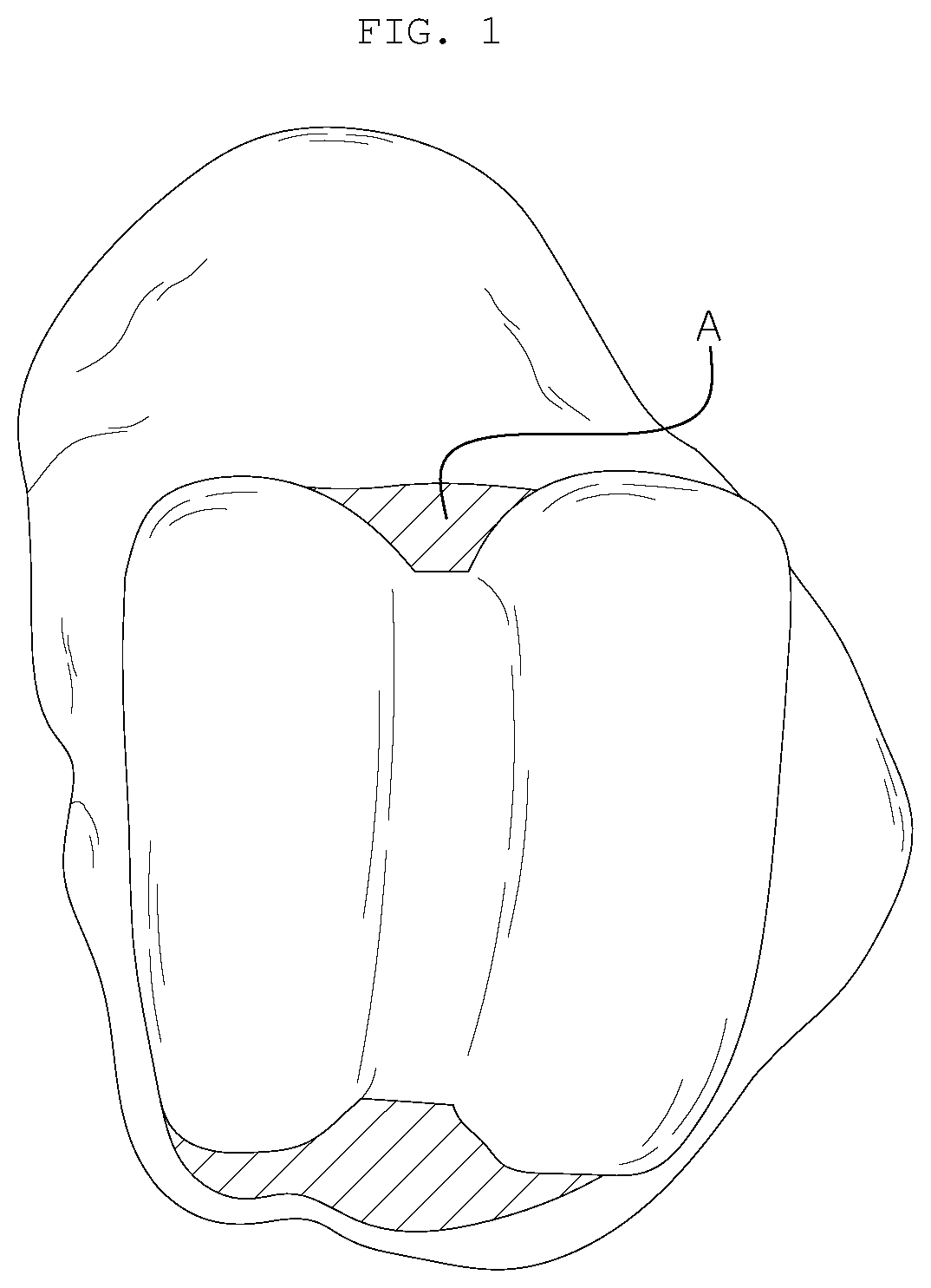
[0077]FIG. 1 is a plan view showing...


PUM


Abstract

The present disclosure relates to an artificial ankle joint talus component and, more particularly, to an artificial ankle joint talus component including a joint surface in contact with an insert and a contact surface in contact with a bone, wherein the contact surface may be formed to be complementary to a resected surface of a talus so as to cover the entire resected surface, thereby dispersing stress, and reducing after-effects of surgery, such as osteolysis, heterotopic ossification, or the like.

Description

BACKGROUND OF THE INVENTION1. Field of the invention[0001]The present disclosure relates to an artificial ankle joint talus component and, more particularly, to an artificial ankle joint talus component including a joint surface in contact with an insert and a contact surface in contact with a bone, wherein the contact surface is formed to be complementary to a resected surface of a talus so as to cover the entire resected surface, thereby dispersing stress, and reducing the after-effects of surgery, such as osteolysis, heterotopic ossification, or the like.2. Description of the Prior Art[0002]In the case where the ankle joint fails to execute its intrinsic function due to various causes such as degenerative arthritis, post-traumatic arthritis, rheumatoid arthritis, and the like of an ankle, arthroplasty is performed using an artificial ankle joint. Clinic trials for artificial ankle joint arthroplasty, which started in the 1970s did not meet expectations because many complications ...

Claims


Application Information

Patent Timeline
Patent Type & Authority Applications(United States)
IPC IPC(8): A61F2/42
CPCA61F2002/3093A61F2002/4207A61F2002/30138A61F2002/30878A61F2/4202A61F2/42A61F2002/30843
Inventor LEE, KEUN-BAESHIN, TAE-JIN
Owner CORENTEC
Why Eureka
Try Eureka