Eureka AIR delivers breakthrough ideas for toughest innovation challenges, trusted by R&D personnel around the world.

Multi-frequency acoustic interrogation for azimuthal orientation of downhole tools

Active Publication Date: 2020-06-25
BAKER HUGHES INC
View PDF0 Cites 1 Cited by
  • Summary
  • Abstract
  • Description
  • Claims
  • Application Information

AI Technical Summary

Benefits of technology

The patent is about detecting the location of an optical fiber that has an acoustic sensor. It describes an apparatus that emits two signals with different frequencies, which are rotated around a borehole where the optical fiber is placed. The signals are then received by the fiber and frequency-multiplied to create a third signal. The phase difference between the second and third signals is then used to determine the location of the optical fiber. The technical effect is a more accurate and efficient way to locate underground optical fibers using acoustic sensors.

Problems solved by technology

Unfortunately, without knowledge of the azimuthal orientation of the optical fiber with respect to the perforation tool, the perforation tool may damage the optical fiber while perforating the casing.

Method used


Image

  • Multi-frequency acoustic interrogation for azimuthal orientation of downhole tools
  • Multi-frequency acoustic interrogation for azimuthal orientation of downhole tools
  • Multi-frequency acoustic interrogation for azimuthal orientation of downhole tools

Examples


embodiment 1

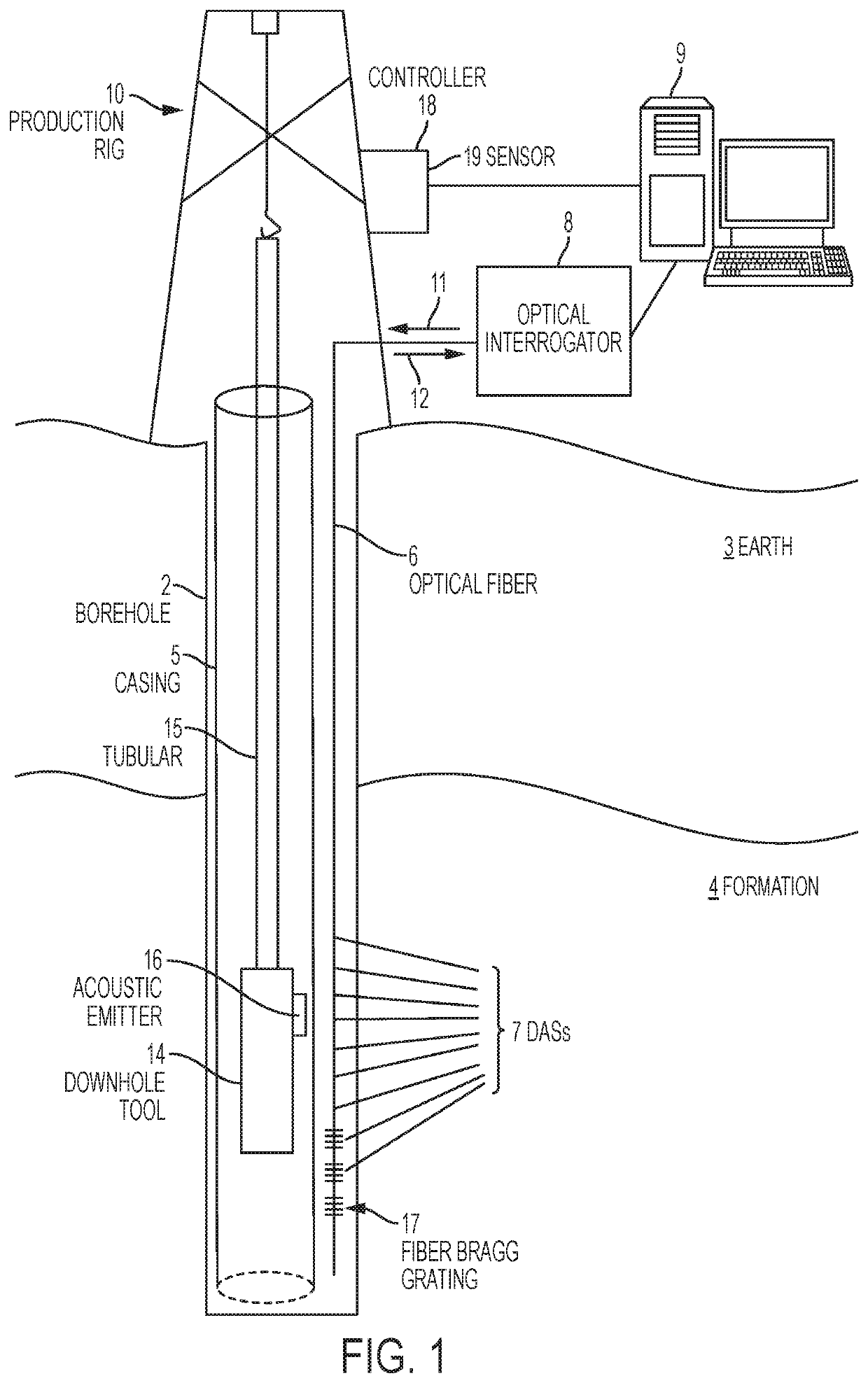
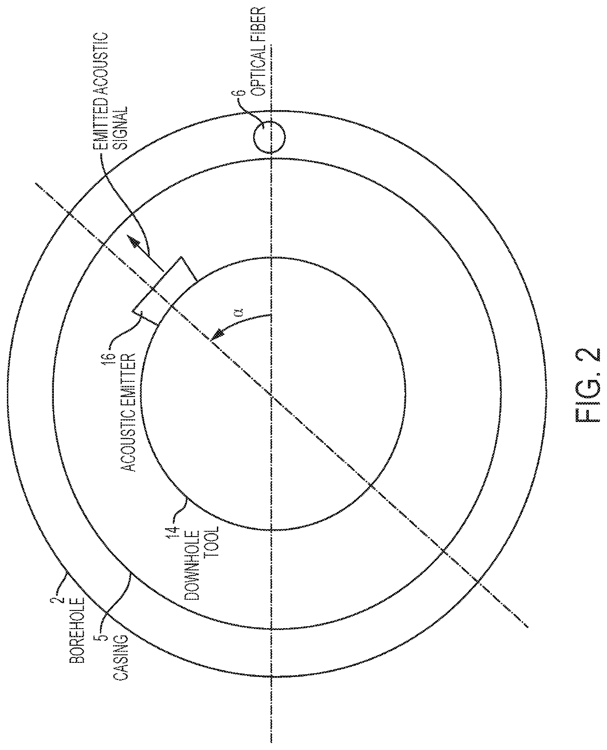
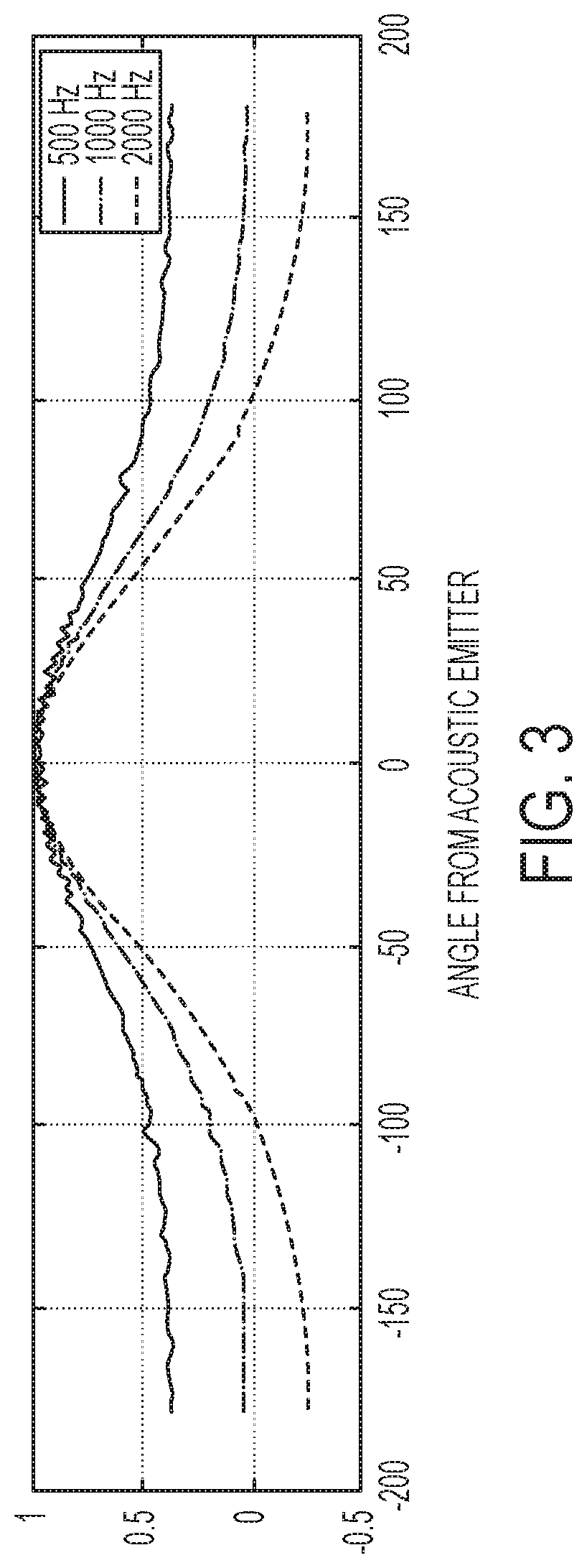
[0030]An apparatus for detecting a location of an optical fiber having an acoustic sensor disposed subsurface to the earth, the apparatus comprising: a carrier configured to be conveyed in a borehole penetrating the earth; an acoustic emitter disposed on the carrier and configured to emit a first emitted acoustic signal having a first frequency and a second emitted acoustic signal having a second frequency that is higher than the first frequency, wherein the carrier and / or the acoustic emitter are configured such that the first and second emitted acoustic signals are azimuthally rotated around the borehole; an optical interrogator configured to interrogate the optical fiber to receive an acoustic measurement that provides a first received signal in response to the first emitted acoustic signal and a second received signal in response to the second emitted acoustic signal, the acoustic measurement being performed by the acoustic sensor at a depth within a selected range of a depth of...

embodiment 2

[0031]The apparatus according to claim 1, further comprising a display configured to display the location to a user.

embodiment 3

[0032]The apparatus according to claim 1, wherein the carrier and / or the acoustic emitter are configured such that the first and second emitted acoustic signals are azimuthally rotated continuously around the borehole.


PUM


Abstract

An apparatus for detecting a location of an optical fiber having an acoustic sensor disposed subsurface to the earth includes an acoustic emitter configured to emit a first signal having a first frequency and a second signal having a second frequency that is higher than the first frequency, the first and second emitted acoustic signals being azimuthally rotated around the borehole and an optical interrogator configured to interrogate the optical fiber to receive an acoustic measurement that provides a corresponding first received signal and a corresponding second received signal. The apparatus also includes a processor configured to (i) frequency-multiply the first received signal to provide a third signal having a third frequency within a selected range of the second frequency, (ii) estimate a phase difference between the second received signal and the third signal, and (iii) correlate the phase difference to the location of the optical fiber.

Description

CROSS REFERENCE TO RELATED APPLICATIONS[0001]This application claims the benefit of U.S. Application No. 62 / 505,398, filed on May 12, 2017, which is incorporated herein by reference in its entirety.BACKGROUND[0002]Boreholes are drilled into earth formations for various purposes such as hydrocarbon production, geothermal production, and carbon dioxide sequestration. Distributed acoustic sensors embodied in an optical fiber may be disposed in a borehole such as between a casing lining the borehole and an earth formation in order to provide data useful in the utilization of the earth formation. When a casing is used, a perforation tool may be used to perforate the casing to gain access to the formation. Unfortunately, without knowledge of the azimuthal orientation of the optical fiber with respect to the perforation tool, the perforation tool may damage the optical fiber while perforating the casing. Hence, it would be well received in industries making use of the earth formations if a...

Claims


Application Information

Patent Timeline
IPC IPC(8): E21B47/09G01V1/22G01V1/46G01V1/50E21B43/119
CPCE21B43/119E21B47/095G01V1/226G01V1/50G01V2210/21G01V2210/1299G01V2210/1429G01V2210/1214G01V1/46E21B47/09G01V1/159G01V1/208G01V1/48G01V1/52G01V2210/626E21B47/113E21B47/10
Inventor COOPER, DANIEL BOYDRAUM, MATTHEW THOMAS
Owner BAKER HUGHES INC
Why Eureka
Eureka Blog
Learn More