Rotary heat exchanger and system thereof

a heat exchanger and rotary technology, applied in the field of cooling systems, can solve the problems of limited overall machine size, limited fan evolution, and limited airflow, and achieve the effect of reducing the temperature of the fluid passing

Active Publication Date: 2020-06-25
DEERE & CO
View PDF0 Cites 2 Cited by
  • Summary
  • Abstract
  • Description
  • Claims
  • Application Information

AI Technical Summary

Benefits of technology

[0011]In a further embodiment of the present disclosure, a cooling system of a vehicle, includes an engine for generating power; a pump for pumping a fluid; and a rotary heat exchanger for cooling the fluid, the rotary heat exchanger manufacturing by a three-dimensional process and comprising a hub; a fan comprising a plurality of fan blades integrally coupled to the hub and extending radially outwardly therefrom; a heat exchanger comprising a plurality of heat exchanger sections, the heat exchanger including a plurality of cooling fins for receiving a flow of air from the fan; and a rotary manifold coupled to the hub, the rotary manifold comprising a fluid passage defined therein for conveying the fluid from the pump to the heat exchanger; wherein each of the plurality of heat exchanger sections is located between two of the plurality of fan blades; wherein, the rotary heat exchanger is rotatably driven to direct the air through the plurality of cooling fins to reduce a temperature of the fluid passing through the heat exchanger. A mechanical or electrical motor may convey rotary motion to the rotary heat exchanger.
[0012]In one example of this embodiment, one or more rotary heat exchangers may be axially aligned with the first rotary heat exchanger, the second rotary heat exchanger positioned to receive at least a portion of the flow of air exiting the first rotary heat exchanger.

Problems solved by technology

Moreover, fans have not evolved much either.
Over the years, particularly as machine size and design has changed, the conventional cooling packages have resulted in limitations and often obstacles to the overall machine.
In particular, these conventional systems often lead to constraints on operator visibility, machine size, and component packaging space.

Method used


Image

  • Rotary heat exchanger and system thereof
  • Rotary heat exchanger and system thereof
  • Rotary heat exchanger and system thereof

Examples


Embodiment Construction

[0025]The embodiments of the present disclosure described below are not intended to be exhaustive or to limit the disclosure to the precise forms in the following detailed description. Rather, the embodiments are chosen and described so that others skilled in the art may appreciate and understand the principles and practices of the present disclosure.

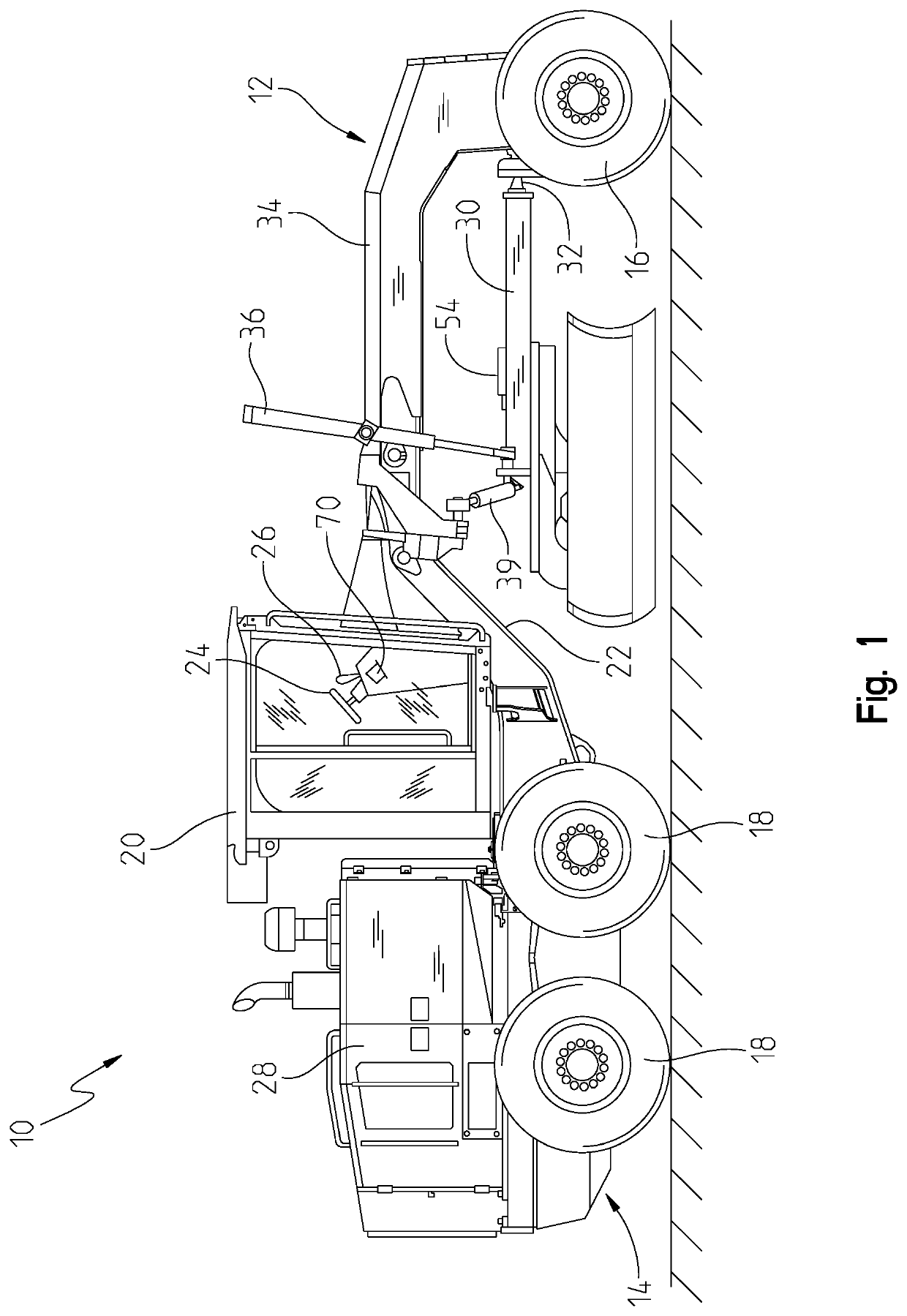
[0026]Referring to FIG. 1, a motor grader 10 is shown including front and rear frames 12 and 14, respectively, with the front frame being supported on a pair of front wheels 16, and with the rear frame being supported on right and left tandem sets of rear wheels 18. An operator cab 20 is mounted on an upwardly and forwardly inclined rear region 22 of the front frame 12 and contains various controls for the motor grader disposed so as to be within the reach of a seated or standing operator. These controls including a steering wheel 24, a lever assembly 26, and a user interface 70 to name a few.

[0027]An engine 28 is mounted on the rear fr...


PUM


Abstract

A rotary heat exchanger includes a hub configured to be rotatably driven by a shaft, a fan including a plurality of fan blades integrally coupled to the hub and extending radially outwardly therefrom, and a heat exchanger including a plurality of heat exchanger sections. The heat exchanger includes a plurality of cooling fins for receiving air from the fan. Each of the plurality of heat exchanger sections is located between two of the plurality of fan blades. The hub, the fan, and the heat exchanger are integrally formed as a single body by a three-dimensional printing process.

Description

FIELD OF THE DISCLOSURE[0001]The present disclosure relates to a cooling system of a machine, and in particular, to an integrated heat exchanger and rotary airfoil and a system including the same.BACKGROUND OF THE DISCLOSURE[0002]In a motorized vehicle or work machine, conventional cooling packages have not changed significantly over the years. In general, these conventional packages are rectangular boxes and utilize manual processes for manufacturing. Moreover, fans have not evolved much either. There are several types of conventional fans including centrifugal, axial, propeller, tube-axial, vane-axial, etc.[0003]Accordingly, original equipment manufacturers, or OEMs, often build machines requiring these systems for their cooling needs only have these conventional systems available for use. Over the years, particularly as machine size and design has changed, the conventional cooling packages have resulted in limitations and often obstacles to the overall machine. In particular, the...

Claims


Application Information

Patent Timeline
Patent Type & Authority Applications(United States)
IPC IPC(8): F04D29/38F01P5/04F04D29/32F04D19/00
CPCF04D29/386F04D29/329F01P5/04F04D29/30F01P2005/046F04D19/002F01P11/10B60H1/00335B60K11/06F04D29/388F28D11/02F28F5/00F28F2255/18B33Y80/00B60K11/04F01P2070/30F01P3/18F28D11/025
Inventor HENDRON, SCOTT S.WEST, SEAN P.BINDL, REGINALD M.CHERNEY, MARK J.
Owner DEERE & CO
Why Eureka
Try Eureka