a condensation injector

A technology of ejector and main condensation, applied in the direction of injection device, liquid injection device, etc., can solve the problems of reducing the outlet pressure and temperature of working fluid, low efficiency of ORC power generation system, etc., and achieve good results

Active Publication Date: 2016-08-24
广西海岛生态投资有限公司
View PDF7 Cites 0 Cited by
  • Summary
  • Abstract
  • Description
  • Claims
  • Application Information

AI Technical Summary

Problems solved by technology

[0003] The object of the present invention is to provide a condensing injector, which can reduce the outlet pressure and temperature of the working fluid through the condensing injector, and solve the problem of low efficiency of the ORC power generation system

Method used


Image

  • a condensation injector
  • a condensation injector

Examples


Embodiment Construction

[0031] The present invention will be further described in detail below in conjunction with the accompanying drawings, so that those skilled in the art can implement it with reference to the description.

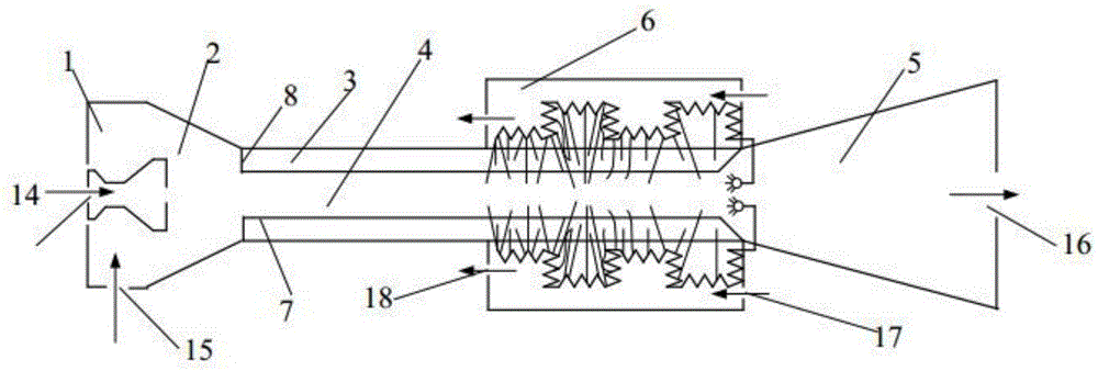
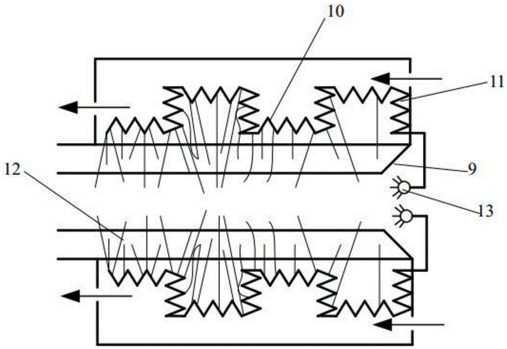
[0032] Such as figure 1 and figure 2 As shown, the present invention discloses a condensation injector, comprising:

[0033] receiving chamber 1, which has a first inlet 14 and a second inlet 15;

[0034] A quantitative valve (not shown), which is arranged at the first inlet 14 .

[0035] A throat chamber 2, one end of which communicates with the receiving chamber 1, the throat chamber 2 being located downstream of the second inlet 15;

[0036] A mixing chamber, one end of which communicates with the other end of the throat chamber 2; the mixing chamber comprises:

[0037] a cylindrical partition 7, which is arranged inside the mixing chamber and extends from one end of the mixing chamber to the other end, thereby dividing the mixing chamber into the first mixing chamber...


PUM


Abstract

The invention discloses a condensation ejector which comprises an accepting chamber, a throat chamber, a mixing chamber, a dispersion chamber, a condensing chamber and an atomizing mechanism, wherein the accepting chamber is provided with a first inlet and a second inlet; one end of the throat chamber is communicated with the accepting chamber, and the throat chamber is located on the down stream of the second inlet; one end of the mixing chamber is communicated with the other end of the throat chamber, one end of the dispersion chamber is communicated with the other end of the mixing chamber, and a first outlet is formed in the other end of the dispersion chamber; the condensing chamber is arranged close to the outer side of the down stream of the mixing chamber in a surrounding mode and comprises a third inlet formed in the down stream end of the condensing chamber, a second outlet formed in the upstream of the condensing chamber, a plurality of main condensing pipes and a plurality of branch condensing pipes, one end of each of the condensing pipes extends into the mixing chamber, the extending directions of the branch condensing pipes are different, the other end of each of the branch condensing pipes is communicated with a main condensing pipe, one end of the main condensing pipe is sealed, and the other end of the main condensing pipe is communicated with the dispersion chamber through a fourth inlet in the dispersion chamber; the atomizing mechanism is provided with a plurality of nozzles formed in the position of the fourth inlet, and the atomizing mechanism is used for atomizing fluid in the main condensing pipe and spraying the fluid in the dispersion chamber.

Description

technical field [0001] The present invention relates to a condensation ejector. Background technique [0002] Waste heat power generation refers to the technology of converting excess heat energy in the production process into electrical energy. The waste heat and pressure utilization project is one of the ten key energy-saving projects in my country's "Special Plan for Energy Conservation Mid- and Long-term Development". It uses the heat or combustible substances in waste gas, waste liquid and other working fluids as a heat source to produce steam for power generation. The waste heat used for power generation mainly includes high-temperature flue gas waste heat, chemical reaction waste heat, waste gas, waste liquid waste heat, and low-temperature waste heat below 200°C. Organic rankine cycle (Organic Rankine Cycle) referred to as ORC, is a Rankine power cycle that uses organic matter instead of water as the working medium to recover low-grade heat energy. Using the organ...

Claims


Application Information

Patent Timeline
Patent Type & Authority Patents(China)
IPC IPC(8): B05B9/04B05B12/00
CPCB05B7/04B05B7/168
Inventor 吴莹
Owner 广西海岛生态投资有限公司
Why Eureka
Try Eureka