Eureka AIR delivers breakthrough ideas for toughest innovation challenges, trusted by R&D personnel around the world.

Soda Carbonation and Dispensation System and Method

a soda water and dispensing system technology, applied in the field of soda beverage dispensing systems, can solve the problems of soda beverage losing appeal, soda water losing carbonation, etc., and achieve the effect of facilitating the creation of the second stage of soda water

Pending Publication Date: 2021-07-15
ABRAHAM HUNTER
View PDF4 Cites 1 Cited by
  • Summary
  • Abstract
  • Description
  • Claims
  • Application Information

AI Technical Summary

Benefits of technology

The present invention is a system and method for carbonating and dispensing soda that solves problems of rapid carbonation loss and foaming with low-pressure delivery. The system includes a first carbonator tank with a carbonation stone and a second pump and motor assembly for mixing first- and second-stage carbonated water. A third pump and motor assembly is provided for delivering carbonated water to a beverage dispensing tower. The technical effects of this invention include maintaining constant carbonation through continuous circulation, achieving a constant low fluid temperature, and reducing foaming with low-pressure delivery.

Problems solved by technology

It is well known that a carbonated beverage loses its appeal when carbonation is expelled and the beverage “goes flat”.
With current beverage fountain systems, soda water loses carbonation because it becomes stagnant and it is not continuously chilled.
High pressure and high temperature dispensation also cause excessive foaming when the beverage is dispensed, which causes rapid carbonation loss.
Consequently, typical fountain beverages lose their appeal soon after they are dispensed.

Method used

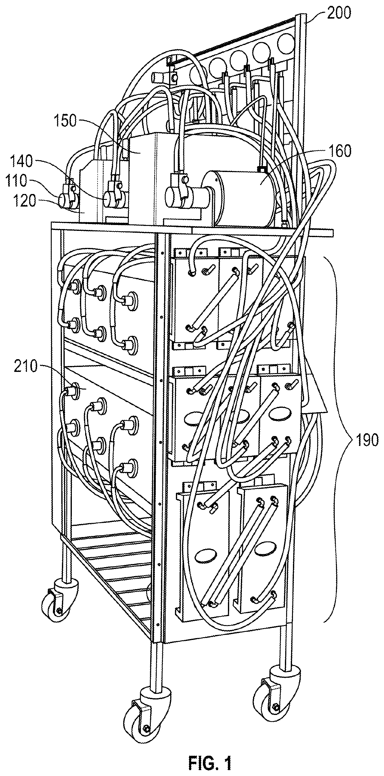
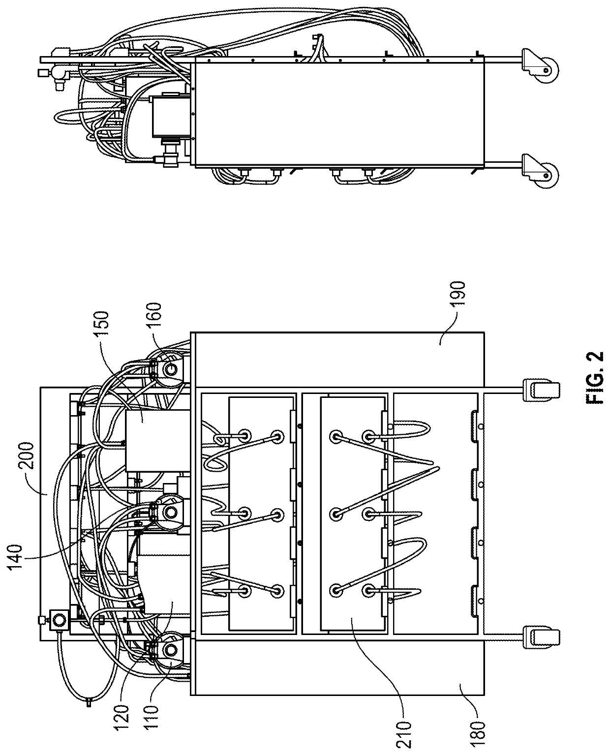
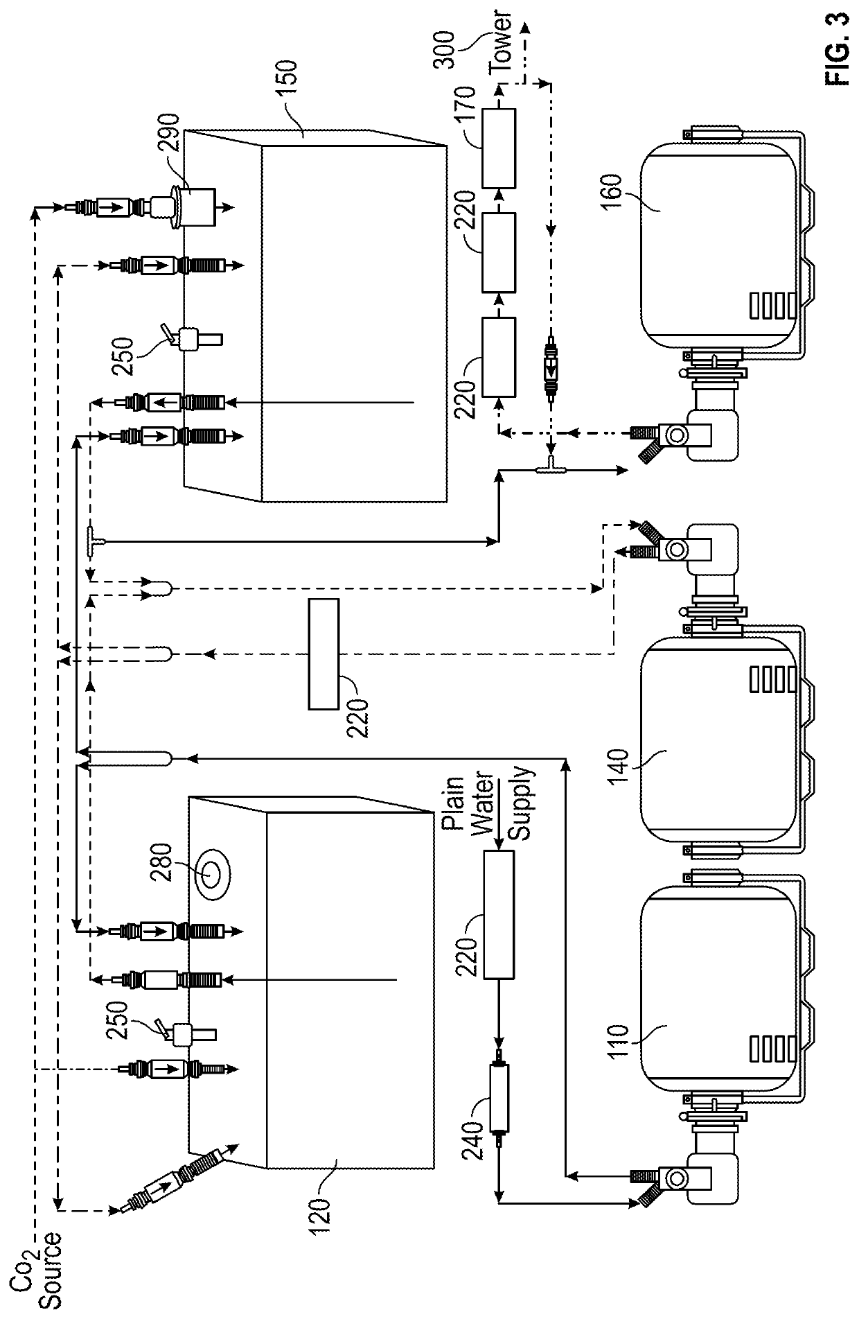

Image

  • Soda Carbonation and Dispensation System and Method
  • Soda Carbonation and Dispensation System and Method
  • Soda Carbonation and Dispensation System and Method

Examples


Embodiment Construction

[0029]For a further understanding of the nature and function of the embodiments, reference should be made to the following detailed description. It will be readily appreciated that the embodiments are well adapted to carry out and obtain the ends and features mentioned as well as those inherent herein. It is to be understood, however, that the present invention is embodied in various forms. Therefore, persons of ordinary skill in the art will realize that the following disclosure is illustrative only and not in any way limiting, as the specific details disclosed herein provide a basis for the claims and a representative basis for teaching to employ the present invention in virtually any appropriately detailed system, structure or manner. It should be understood that the devices, materials, methods, procedures, and techniques described herein are presently representative of various embodiments. Other embodiments of the disclosure will readily suggest themselves to such skilled person...


PUM

PropertyMeasurementUnit
Temperatureaaaaaaaaaa
Pressureaaaaaaaaaa
Volumetric flow rateaaaaaaaaaa

Abstract

A soda carbonation and dispensation system and method are provided. The system includes a carbonated water pump and motor assembly operable to draw fresh water into carbonator tanks and circulate the water through a chiller system. A carbon dioxide source is connected to the carbonator tanks to produce carbonated water. The system also includes a water level sensor connected to a controller, a plurality of syrup containers, a syrup pump, syrup regulator valves, a brix capacitor, a dispensing tower and faucets connected to the dispensing tower housing. The controller operates the water pump and motor assembly to maintain a water level within a predetermined range and to maintain continuous flow and refrigeration of the carbonated water, which optimizes carbonation. The brix capacitor receives chilled carbonated water and chilled syrup in separate lines. Carbonated water is circulated to the faucets through a manifold in the brix capacitor and then circulated back into the carbonator tanks. Valves are provided in the brix capacitor to manipulate carbonated water and syrup flow rates and pressures into the faucets. The system maintains the carbonated water and syrup at a refrigerated temperature and a predetermined maximum pressure. When a faucet is opened, the carbonated water and syrup mix as they flow laminarly into a container. The result is consistently optimum carbonation when the beverage is dispensed.

Description

CROSS REFERENCE TO RELATED APPLICATIONS[0001]This application claims priority to U.S. Provisional Patent Application No. 62 / 906,065, filed Sep. 25, 2019, the entirety of which is incorporated herein by reference.BACKGROUND[0002]The present invention relates to carbonated beverage dispensation systems, commonly called soda fountains, which prepare and dispense carbonated beverages on-demand. More specifically, the present invention is directed to a system and method for making carbonated water, conveying chilled, low pressure carbonated water and flavored syrup to a dispensing tower, and mixing the carbonated water and syrup as they are dispensed into a container.[0003]Carbonated beverages are typically prepared when pressurized carbonated water and flavored syrup are held within separate tanks and then mixed as they are pumped through a single discharge spout or faucet. A user selects the beverage by pressing a button or activating a lever below a discharge spout, the corresponding ...

Claims


Application Information

Patent Timeline
IPC IPC(8): B67D1/08B01F3/04B67D1/00
CPCB67D1/0857B67D1/0061B01F3/04808B67D1/0862B67D2210/00139B67D2210/0006B67D1/1422B67D1/1472B67D1/0027B67D1/0031B01F23/2362
Inventor ABRAHAM, HUNTERABRAHAM, III, MARTIN J
Owner ABRAHAM HUNTER
Why Eureka
Eureka Blog
Learn More