Optical Lens for Illumination Purposes

Inactive Publication Date: 2020-06-25
SWAREFLEX
View PDF7 Cites 0 Cited by
  • Summary
  • Abstract
  • Description
  • Claims
  • Application Information

AI Technical Summary

Benefits of technology

The present invention provides lenses that offer better control over the "color-over-angle" effect, which means that color gradients can be minimized when using illumination. Additionally, the lenses have a dropping-off edge which helps to prevent the formation of soil residues that can negatively impact the efficiency and light distribution. Overall, these lenses offer improved performance in various applications such as traffic lighting.

Problems solved by technology

The illumination of traffic tunnels is a challenge for optics design and lighting design because of strict illumination standards.
However, the document does not contain any disclosure directed to the design of an optical lens.
However, the prior art has considerable problems: Thus, in particular, part of the luminous flux is absorbed by the cover hood, whereby the efficiency of the lamp decreases to below 60%.
The partial mirroring of the lateral surface is also disadvantageous, because a complex lens shape must be used in order to obtain the desired light deflection onto the mirrored surface.
Further, the partial mirroring of individual bounded lateral surfaces have a negative effect on the ability to produce the optical system.
In general, previous optical systems have the disadvantage that their light distributions do not have the optimum precision and thus lead to luminous flux losses or disturbing dazzling.
These disadvantages often complicate or prevent the use of such optical concepts in traffic tunnels.

Method used


Image

  • Optical Lens for Illumination Purposes
  • Optical Lens for Illumination Purposes
  • Optical Lens for Illumination Purposes

Examples


example 1

Comparative Examples C1 to C3

[0094]In order to further work out the differences of the novel optical system, light-technological simulations of three classical lenses and the novel lens system were performed. The simulation set-up is identical for all lens systems and is structured as follows:

[0095]1. Placing the LED into the origin of coordinates.

[0096]2. Setting the lens CAD geometry.

[0097]3. Adjusting the reference coordinates of the LED lens system.

[0098]4. Acquiring the light intensity distribution in polar coordinates.

[0099]5. Placing a rectangular area detector at a constant distance and with a constant size to calculate the luminous density distribution.

[0100]FIG. 3 shows the results of the light-technological simulation of the different optical systems. Lens system 1 (FIG. 3a) and lens system 1 with a cover (FIG. 3b) are existing lens systems that are employed in traffic. The lens system 2 (FIG. 3c) represents a simulation concept of a pure lens optical system, which narrow...


PUM


Abstract

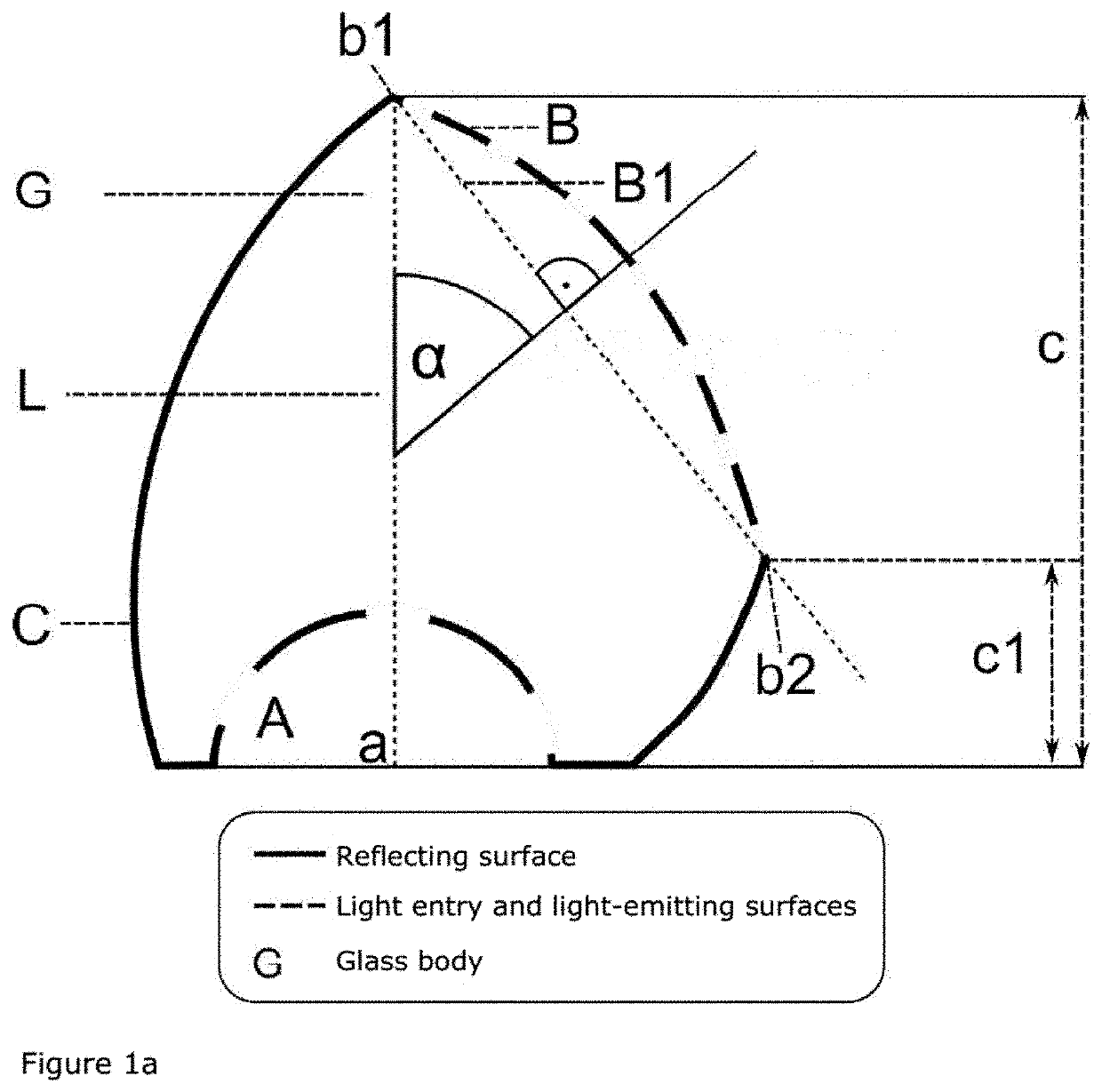
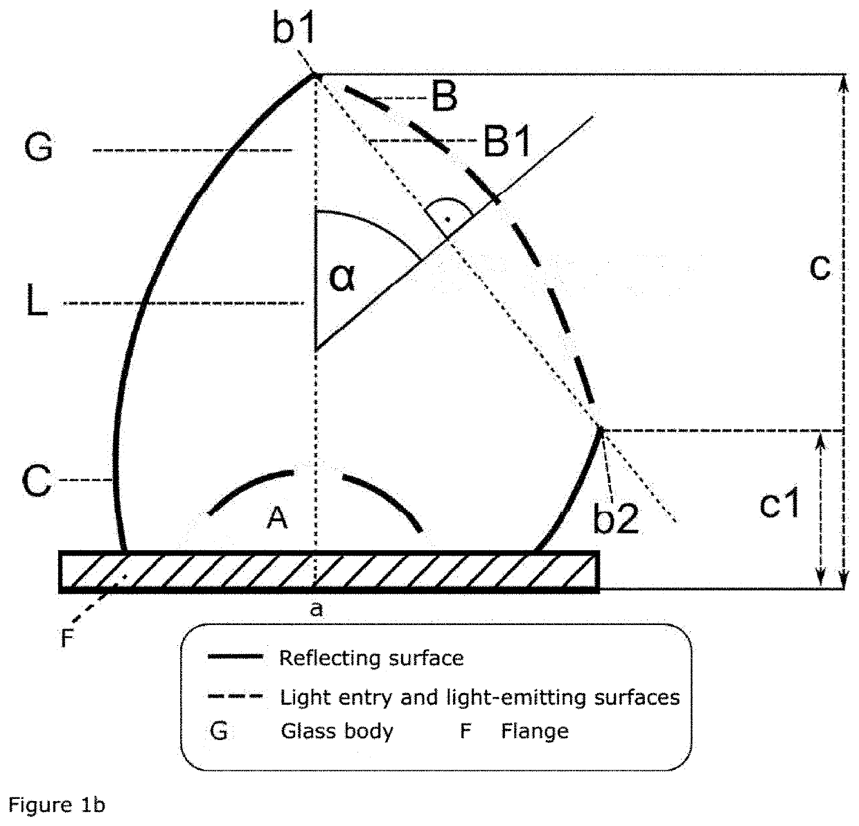
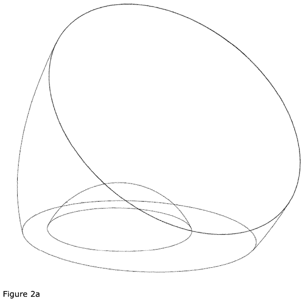
Optical lenses for illumination purposes (L) are proposed, comprising a lateral surface (C) and a light exit surface (B), wherein the underside is shapes in a plane fashion and has an optical relevant cutout for receiving a light source, which is distinguished by the fact that the lens (L) has a lateral surface (C) that is wholly reflectively coated, and has a light exit surface (B) having the two vertices (b1) and (b2), wherein (b1) and (b2) represent respectively the highest and lowest vertices upon the transition from the light exit surface (B) to the lateral surface (C).

Description

FIELD OF THE INVENTION[0001]The invention relates to the field of traffic engineering, and relates to specifically designed lenses for use in illumination devices for tunnel systems, and to the illumination devices containing such lenses.PRIOR ART[0002]The illumination of traffic tunnels is a challenge for optics design and lighting design because of strict illumination standards. In particular, the tunnel entry zone is critical, since the human eye has to adapt to the quickly changing light levels (adaptation). In addition, the perceived dazzling during the drive through a tunnel is an important factor, which is standardized by the authorities.[0003]An illumination concept that has become established in recent years in the tunnel field is the so-called pro-beam and counter-beam principle. In the pro-beam principle, the projection of the main emission direction onto the road runs parallel to the direction of driving, while the projection is antiparallel to the direction of driving i...

Claims


Application Information

Patent Timeline
IPC IPC(8): F21V5/04F21V5/08G02B19/00
CPCF21V5/048G02B19/0061F21W2131/103F21W2131/101F21V5/08G02B19/0028F21Y2115/10F21V5/04F21W2131/00
Inventor HAUSER, DANIELFLIR, ANTONEBNER, WALTER
Owner SWAREFLEX
Why Eureka
Try Eureka