Rail-launching munition release

a technology of rail-launching munition and payload release, which is applied in the direction of rocket launchers, torpedo launchers, weapons, etc., can solve the problems of unsuitable use of conventional vertical launch devices, unintended angular momentum of payloads, and aircraft with doors arranged in the sides or rear of the fuselage, so as to achieve more controlled and accurate launching of payloads and greater payload accuracy

Active Publication Date: 2020-06-25
VERTEX AEROSPACE LLC
View PDF0 Cites 4 Cited by
  • Summary
  • Abstract
  • Description
  • Claims
  • Application Information

AI Technical Summary

Benefits of technology

[0006]The rail launching mechanisms described herein enables more controlled and accurate launching of a payload as compared with conventional rail launching systems. An exemplary dual rail launching mechanism includes vertically offset rails that separately engage payload lugs of the payload. Arranging the rails to be vertically offset provides a horizontal, or nearly horizontal, launching arrangement in which either a simultaneous release of the payload lugs from the rails occurs, or a controlled disengagement of each lug occurs. Simultaneously diseng

Problems solved by technology

However, conventional launching devices may not be suitable for use in applications that do not have conventional launching platforms such as wing hardpoints.
Additionally, an aircraft with doors arranged in the sides or rear of the fuselage may not be suitable for utilizing conventional vertical launching devices.
However, conventional rail launchers are disadvantageous in that a rear lug may disengage from the rail before the front lug, resulting in binding in the rail and a nose-up pitch rotation of the payload, while also imparting unintended angular momentum to the payload.
Another disadvantage of conventional rail launchers is that the conventional rail launcher may not

Method used


Image

  • Rail-launching munition release
  • Rail-launching munition release
  • Rail-launching munition release

Examples


Embodiment Construction

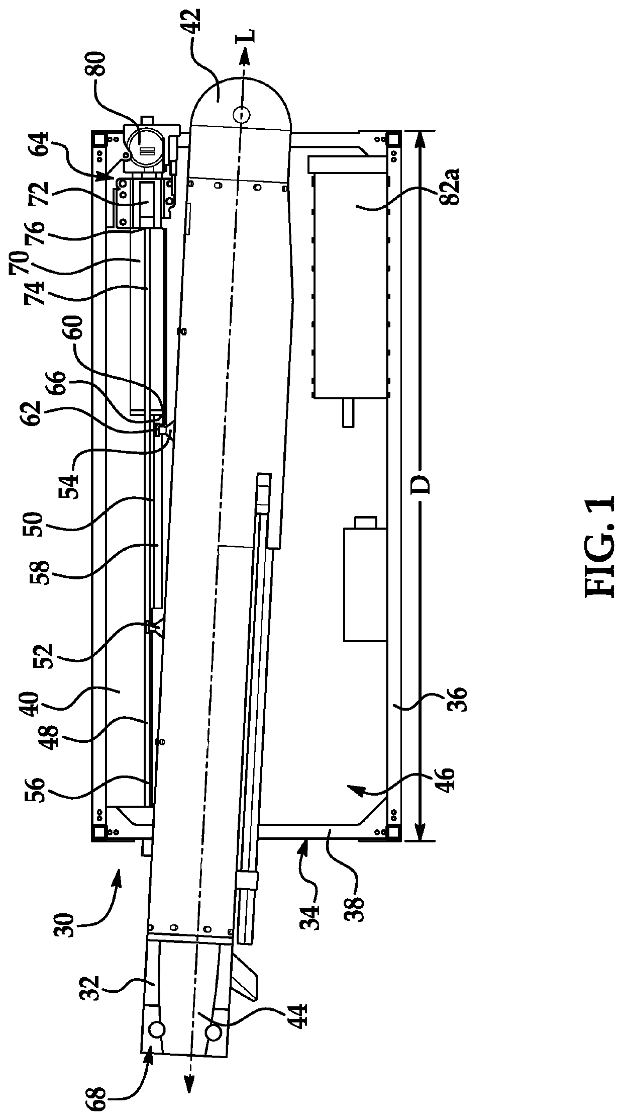
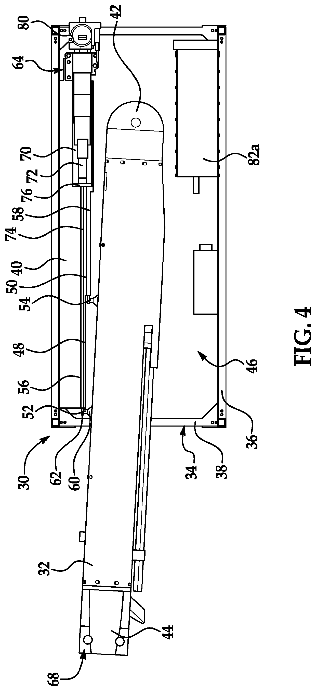
[0058]The principles described herein have particular application in launching systems that are suitable for use in various applications. Suitable applications may include land vehicles, aircrafts, surface ships, underwater vehicles, and hypersonic vehicles that are configured to launch a payload. In addition to powered and unpowered air-to ground payloads, or stores, air-to-ground rockets or air-to-air missiles may be suitable applications. Exemplary applications may be military applications or commercial applications using military craft or commercial craft such as commercial planes, cargo planes, helicopters, balloons, and other aerostats for delivery of payloads. Many different types of launching platforms may be suitable and the platforms may be manned or autonomous. Examples of launchable payloads include munitions, underwater vehicles, flares, chaff, drones, and any other non-lethal effectors or cargo (e.g., medical supplies, food, emergency kits, humanitarian goods, etc.) th...


PUM


Abstract

A rail launch mechanism and method for launching a payload is configured to release payload lugs of a payload from a platform. A rack for launching a payload includes multiple rails that separately engage lugs in the respective payload of the rails, and a force actuator for launching the payload by accelerating the payload along the rails, causing the lugs to separate from the respective rails. A launching system for launching the payload from the platform may include a rail, at least one payload release shoe that carries a payload lug along the rail, and a force actuator for accelerating the payload release shoe such that inertia of the payload causes the payload lug to be released from the payload release shoe.

Description

FIELD OF THE INVENTION[0001]The invention relates to payload release mechanisms and methods of carriage and releasing payloads.DESCRIPTION OF THE RELATED ART[0002]Various applications may use deployable payloads that are releasable from a stationary or moving platform. For example, military applications that use land vehicles, aircrafts, surface ships, or underwater vehicles may include deployable munitions. In an aircraft application, munitions are conventionally dropped vertically such that the carriage of the munitions is restricted to locations of the airframe of the aircraft that are under wing hardpoints, fuselage hardpoints, or bomb bays having doors that face downwardly. However, conventional launching devices may not be suitable for use in applications that do not have conventional launching platforms such as wing hardpoints. Additionally, an aircraft with doors arranged in the sides or rear of the fuselage may not be suitable for utilizing conventional vertical launching d...

Claims


Application Information

Patent Timeline
IPC IPC(8): F41F3/04
CPCF41F3/0406B64D1/06B64D7/08F41F3/06F41F3/065F41F3/08
Inventor CAMPBELL, DAVID R.WRIGHT, PHILIP C.BAILEY, ROBERT A.TRAYLOR, JAMES
Owner VERTEX AEROSPACE LLC
Why Eureka
Try Eureka