Interior permanent magnet electric motor and rotor included therein

a permanent magnet electric motor and electric motor technology, applied in the direction of dynamo-electric machines, magnetic circuit rotating parts, magnetic circuit shape/form/construction, etc., can solve the problems of difficult to enhance these two characteristics simultaneously, increase manufacturing cost, and large increase in manufacturing cost, so as to maximize fuel efficiency and quietness of vehicles, enhance motor efficiency

Active Publication Date: 2020-07-02
HYUNDAI MOTOR CO LTD +1
View PDF0 Cites 1 Cited by
  • Summary
  • Abstract
  • Description
  • Claims
  • Application Information

AI Technical Summary

Benefits of technology

[0008]The present disclosure is configured to effectively enhance motor efficiency and to substantially improve NVH performance by changing only some shapes such as a buried structure of a permanent magnet inside an electric motor, thereby maximizing fuel efficiency and quietness of a vehicle.

Problems solved by technology

However, since motor efficiency and the NVH performance are generally in a trade-off relationship, it is difficult to enhance these two characteristics simultaneously.
In order to enhance the motor efficiency, methods such as changing materials of an electric steel plate and a permanent magnet, enhancing a fill factor (a coil area per a slot area), and improving a bearing for minimizing a mechanical hand are applied thereto, but these methods have a disadvantage in that a manufacturing cost greatly increases.
Meanwhile, as a method for improving the NVH performance, there are methods for increasing the number of poles / slots, applying a stator / rotor core skew (spin stack), and the like, but in this case, there are the disadvantages in that a manufacturing cost increases and motor efficiency may be reduced.

Method used


Image

  • Interior permanent magnet electric motor and rotor included therein
  • Interior permanent magnet electric motor and rotor included therein
  • Interior permanent magnet electric motor and rotor included therein

Examples


experimental example 1

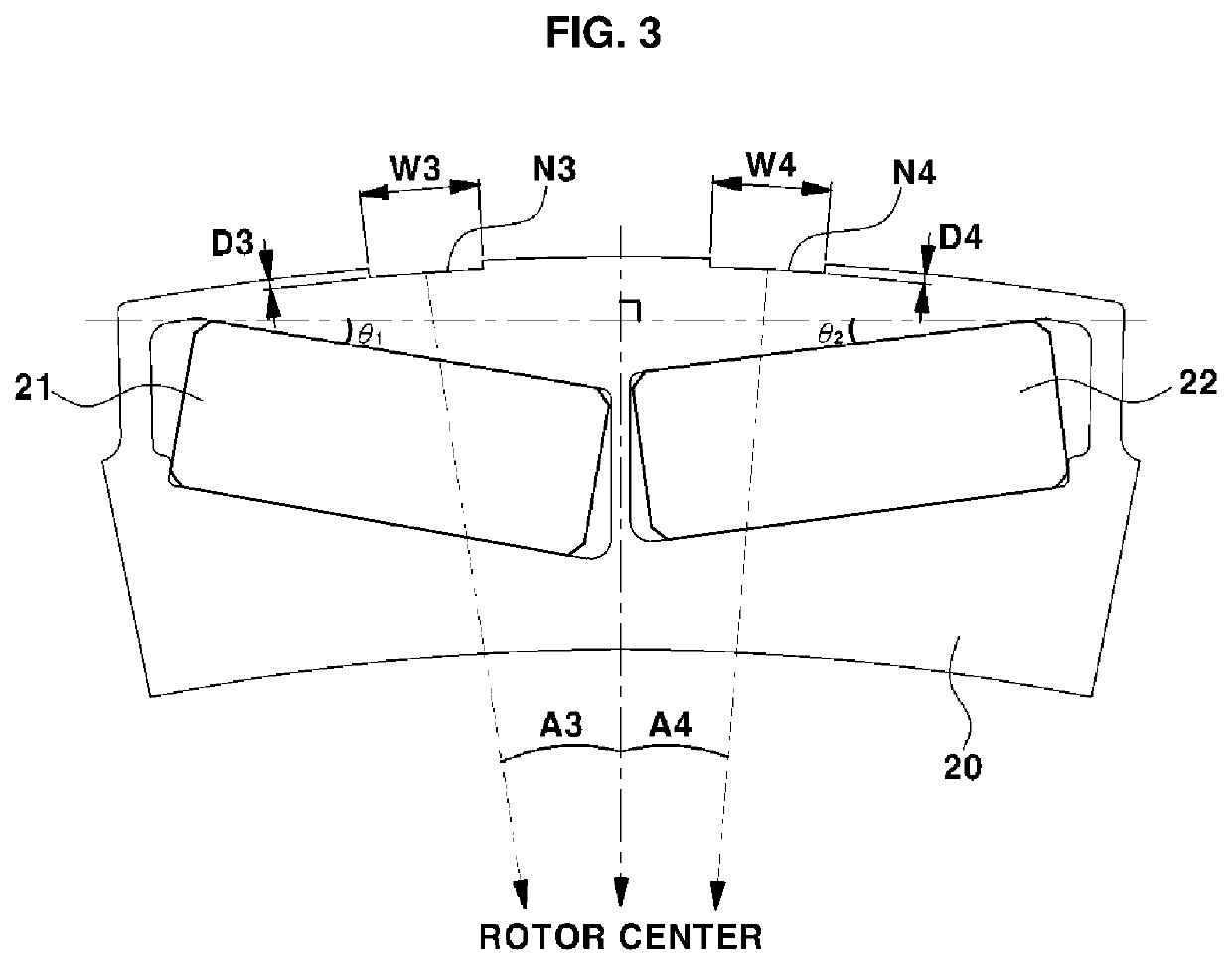
[0049]As illustrated in FIG. 3, motor efficiency and torque ripple were measured for the asymmetric permanent magnet buried type rotors in which two permanent magnets having different buried angles of the permanent magnet were inserted into one slot part. In particular, the experiment was performed while changing the buried angle of the permanent magnet of the rotor to 5 degrees, 7 degrees, and 10 degrees.

[0050]In addition, the I-type rotor in which the buried angle of the permanent magnet is ‘0’ and the V-type rotor of a symmetric structure in which the buried angle of the permanent magnet is constant were also used as a comparative example, and the respective motor efficiencies and torque ripples were measured.

[0051]Table 1 below illustrates the motor efficiency according to the buried angle of the permanent magnet, Tables 2 and 3 illustrate the torque ripple according to the buried angle of the permanent magnet, and Table 2 illustrates the 48th torque ripple and Table 3 illustrat...

experimental example 2

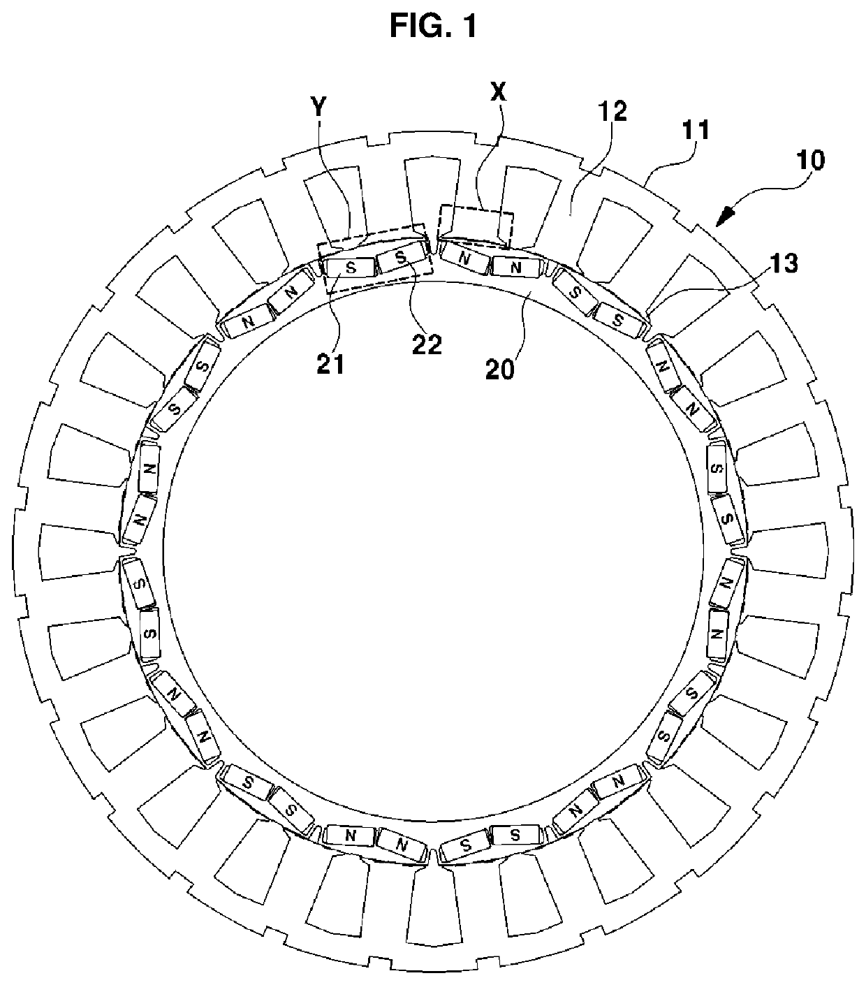
[0073]Changes in a primary cogging torque and a secondary cogging torque were measured by fixing the number of notches formed on the stator 10 and the rotor 20 to two, respectively, and changing the positions of the notches formed on the stator 10 and the rotor 20.

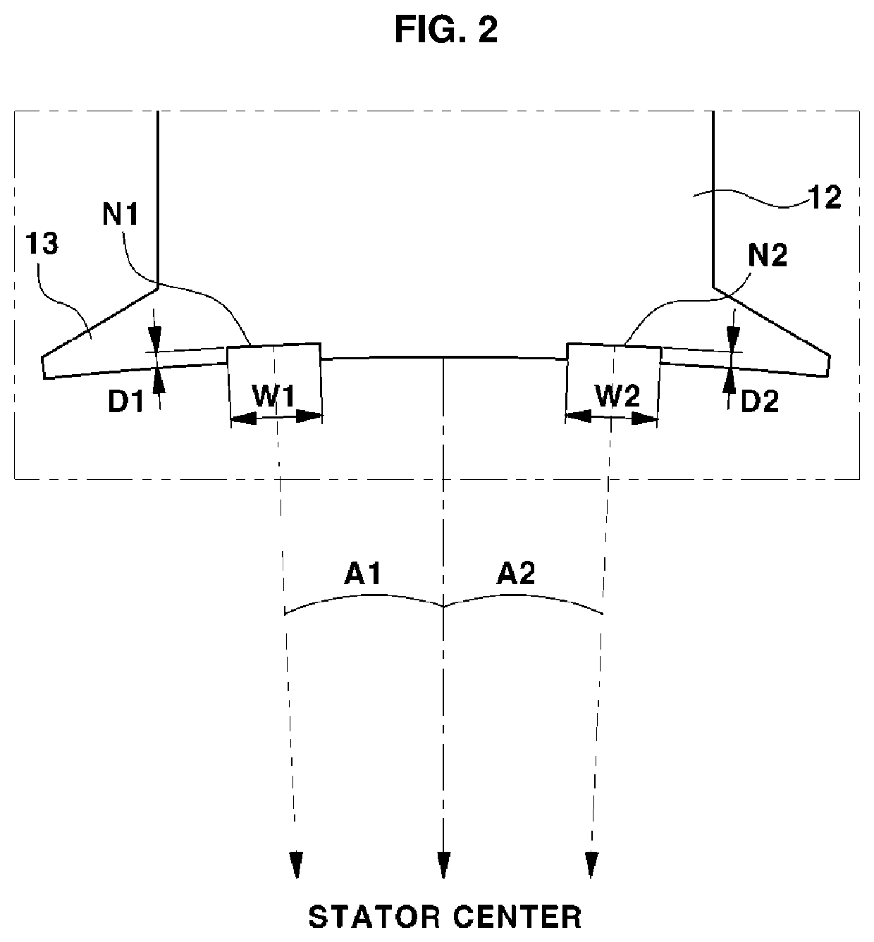
[0074]That is, the widths W1, W2 of the two notches N1, N2 formed on the stator 10 and the widths W3, W4 of the rotor notches N3, N4 formed by two for each one polarity permanent magnet of the rotor 20 were fixed. In addition, the changes in the primary cogging torque and the secondary cogging torque were measured by changing angles A1, A2 formed by the circumferential directional center of the shoe 13 and the center of one stator notches N1, N2 (with respect to the center of the stator 10), and changing angles A3, A4 formed by the circumferential directional center of the slot part of the rotor, that is, the center of a partition wall part for partitioning the permanent magnets and the center of the rotor notches N3, N4 n...

experimental example 3

[0077]Changes in the cogging torque were measured by fixing the number, widths, positions, and the like of the notches of the rotor 20, and by changing the widths W1, W2 of the two notches N1, N2 formed on the stator 10 and the angles A1, A2 formed by the circumferential directional center of the shoe 13 and the centers of the respective stator notches N1, N2 (with respect to the center of the stator 10). In particular, the stator notches N1, N2 were formed at the same width and angle as each other.

[0078]The result of Experimental Example 3 is illustrated in Table 6 below.

TABLE 6Cogging torque [primary + secondary, Nm]Stator NotchWidthStator Notch Angle [deg][mm]22.42.83.23.644.44.85.215.855.244.644.204.104.384.945.636.571.25.855.074.343.793.683.984.615.476.541.45.854.914.043.403.263.584.295.276.501.65.844.743.722.992.843.193.955.076.441.85.834.573.412.612.422.803.624.886.3625.824.403.102.232.012.393.294.686.262.25.804.192.791.851.612.012.964.496.152.45.774.062.551.571.211.612.684.3...


PUM


Abstract

An interior permanent magnet electric motor forms a buried angle of a left permanent magnet of a slot part of a rotor differently from a buried angle of a right permanent magnet of the slot part of the rotor, so as to reduce torque ripple while sufficiently maintaining motor efficiency as compared to an I-type rotor to effectively improve noise, vibration, and harshness performance.

Description

CROSS-REFERENCE TO RELATED APPLICATION[0001]This application claims under 35 U.S.C. § 119(a) the benefit of Korean Patent Application No. 10-2018-0171114 filed on Dec. 27, 2018, the entire contents of which are incorporated herein by reference.BACKGROUND(a) Technical Field[0002]The present disclosure relates to an interior permanent magnet electric motor, more particularly, to a rotor and a stator capable of enhancing efficiency and NVH performance of the interior permanent magnet electric motor.(b) Description of the Related Art[0003]A drive motor for an eco-friendly vehicle typically is an Interior Permanent Magnet (IPM) Motor type to provide high output / high efficiency. In a motor for a vehicle, an important factor to be considered with respect to motor efficiency is Noise, Vibration, and Harshness (NVH) performance. The NVH performance of the motor is also an important performance factor directly related to the driving performance of the vehicle and driver satisfaction.[0004]How...

Claims


Application Information

Patent Timeline
Patent Type & Authority Applications(United States)
IPC IPC(8): H02K1/27
CPCH02K29/03H02K2201/06H02K1/2766H02K21/14H02K1/16H02K2213/03H02K1/26
Inventor DO, SANG HWAKIM, KYOUNG BUMKIM, YEON HOPARK, JAE BUMHONG, NYEON HANLEE, HEE RA
Owner HYUNDAI MOTOR CO LTD
Why Eureka
Try Eureka