Device for wet mechanical separation of a mixture of solid materials of different density

Inactive Publication Date: 2020-07-16
SENTREC HLDG BV
View PDF0 Cites 0 Cited by
  • Summary
  • Abstract
  • Description
  • Claims
  • Application Information

AI Technical Summary

Benefits of technology

The invention provides an improved device for separating solid materials of different densities through wet mechanical means. The device has several technical features including a self-cleaning drum, a reduced number of components, and a simplified maintenance schedule. The device can also be equipped with a nozzle to regulate the amount of separating liquid discharged based on the solid materials being separated. Additionally, the motor for rotating the drum can be positioned in a housing to minimize maintenance requirements. A discharge chute can also be provided to more efficiently separate plastic foil materials from the separating liquid. Overall, the invention provides a more efficient, reliable, and straightforward device for wet mechanical separation of solid materials.

Problems solved by technology

Although the known device efficiently separates lighter from heavier solid materials, the known device requires a large number of components, mostly arranged inside the drum and two motors, one for rotationally driving the drum and the other for rotating the rinsing disc and acceleration disc.
Further, it appears that the hollow drive shaft through which the central discharge tube extends needs regular maintenance as does the inner side of the drum.
In particular solid materials that have sunk towards the bottom of the wall and are passed via the stabilizing disc and the discharge channels formed by the wing-like rotors under the rinsing disc can negatively influence the rotation of the rinsing disc or block the discharge passages.
Thus the known device also requires regular cleaning of the interior of the drum, leading to downtime.

Method used


Image

  • Device for wet mechanical separation of a mixture of solid materials of different density
  • Device for wet mechanical separation of a mixture of solid materials of different density
  • Device for wet mechanical separation of a mixture of solid materials of different density

Examples


Embodiment Construction

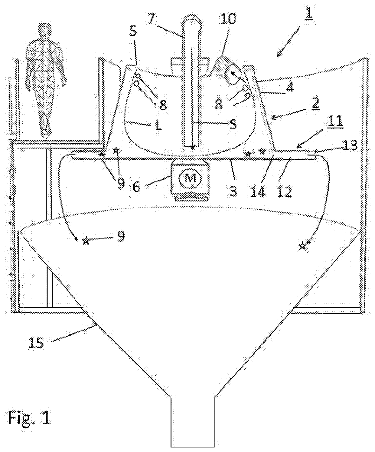
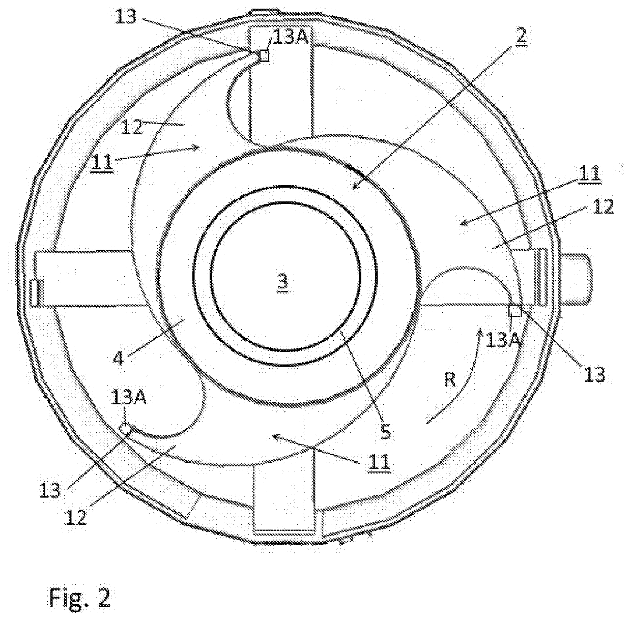
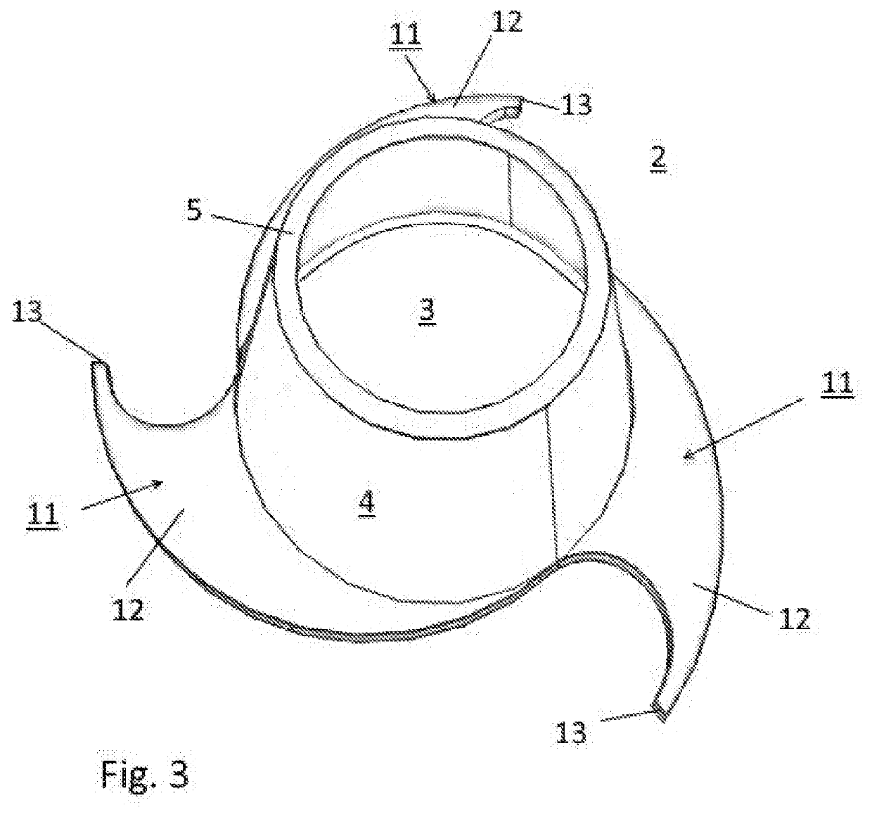
[0017]In FIGS. 1 to 3 a first embodiment of a device 1 for wet mechanical separation of a mixture of solid materials of different density is shown in side view. The device comprises a rotatable drum 2 having a bottom wall 3, a closed peripheral wall 4 and an open top 5 opposite the bottom wall. As e.g. shown in FIGS. 1 and 3 the drum 2 tapers conically upwards and vertically. A motor M is provided for rotating the rotatable drum 2 in a rotation direction R (FIG. 2). In the embodiment shown in FIG. 1 the motor M for rotating the rotatable drum 2 is positioned in a housing 6 below the bottom wall 3 of the drum 2. The housing 6 shields the motor M from the environment. Please note however, that the invention is not restricted to the shown embodiment in which the motor is arranged directly below the bottom wall of the drum, and in other embodiments the motor can e.g. be arranged at the side of the drum outside of a first receptacle (as described below) for receiving heavier solid materi...


PUM


Abstract

A device for wet mechanical separation of a mixture of solid materials of different density comprises a rotatable drum having a bottom wall, a closed peripheral wall and an open top. The drum tapers conically upwards and vertically. A motor is provided for rotating the drum in a rotation direction. A supply supplies a separating liquid with a mixture of solid materials of different density through the open top into the rotatable drum. During operation rotating the drum results in driving the separating liquid with the mixture of solid materials outwardly towards the inner wall of the drum. Depending on their density solid materials to be separated either float on the surface of separating liquid or sink towards the bottom wall and can be discharged and gathered from the top or bottom of the drum, respectively. The device comprises at least one discharge extending radially outwards from the bottom wall of the drum for separating liquid and solid materials that have sunk to the bottom wall.

Description

FIELD OF THE INVENTION[0001]The invention relates to a device for wet mechanical separation of a mixture of solid materials of different density, the materials in particular containing plastics, the device comprising a rotatable drum having a bottom wall, a closed peripheral wall and an open top opposite the bottom wall, said drum tapering conically upwards and vertically, a motor for rotating the rotatable drum in a rotation direction, and a supply for supplying a separating liquid, in particular water, with a mixture of solid materials of different density through the open top into the rotatable drum, the device being arranged for during operation rotating the drum so that as a result of centrifugal force the separating liquid with the mixture of solid materials is driven outwardly towards the inner wall of the drum while depending on their density solid materials to be separated either float on the surface of separating liquid or sink towards the bottom wall, and can be discharge...

Claims


Application Information

Patent Timeline
IPC IPC(8): B03B5/32
CPCB03B5/32
Inventor WOLTERS, HENDRIK
Owner SENTREC HLDG BV
Why Eureka
Try Eureka