

Isolated switching power supply apparatus
- Summary
- Abstract
- Description
- Claims
- Application Information
AI Technical Summary
Benefits of technology
Problems solved by technology
Method used
Image

Examples
first preferred embodiment
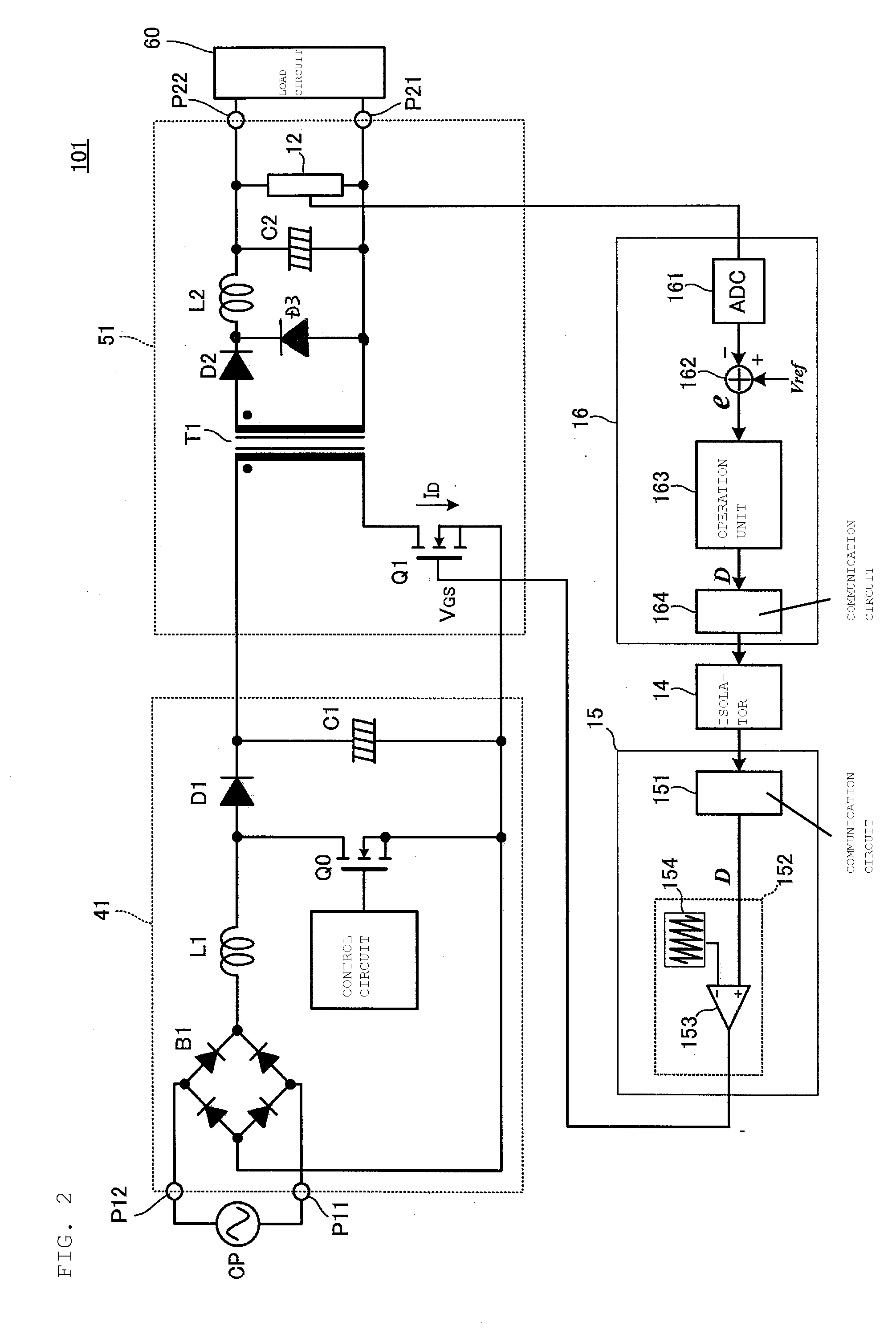
[0031]FIG. 2 is a circuit diagram of an isolated switching power supply apparatus (hereafter simply referred to as a “switching power supply apparatus”) 101 according to a first preferred embodiment of the present invention. The switching power supply apparatus 101 preferably includes a PFC converter 41, a DC-DC converter 51, a primary-side digital control circuit 15, and a secondary-side digital control circuit 16. The primary-side and secondary-side digital control circuits control the PFC converter 41 and the DC-DC converter 51.
[0032]A commercial power supply CP is connected to voltage input units P11 and P12 of the switching power supply apparatus 101. A load 60 is connected to voltage output units P21 and P22 of the switching power supply apparatus 101.
[0033]A diode bridge B1, which full-wave rectifies an input voltage, an inductor L1, a switching element Q0, and a diode D1 define a boost converter circuit. A capacitor C1 defines a smoothing circuit that smoothes an output of t...
second preferred embodiment
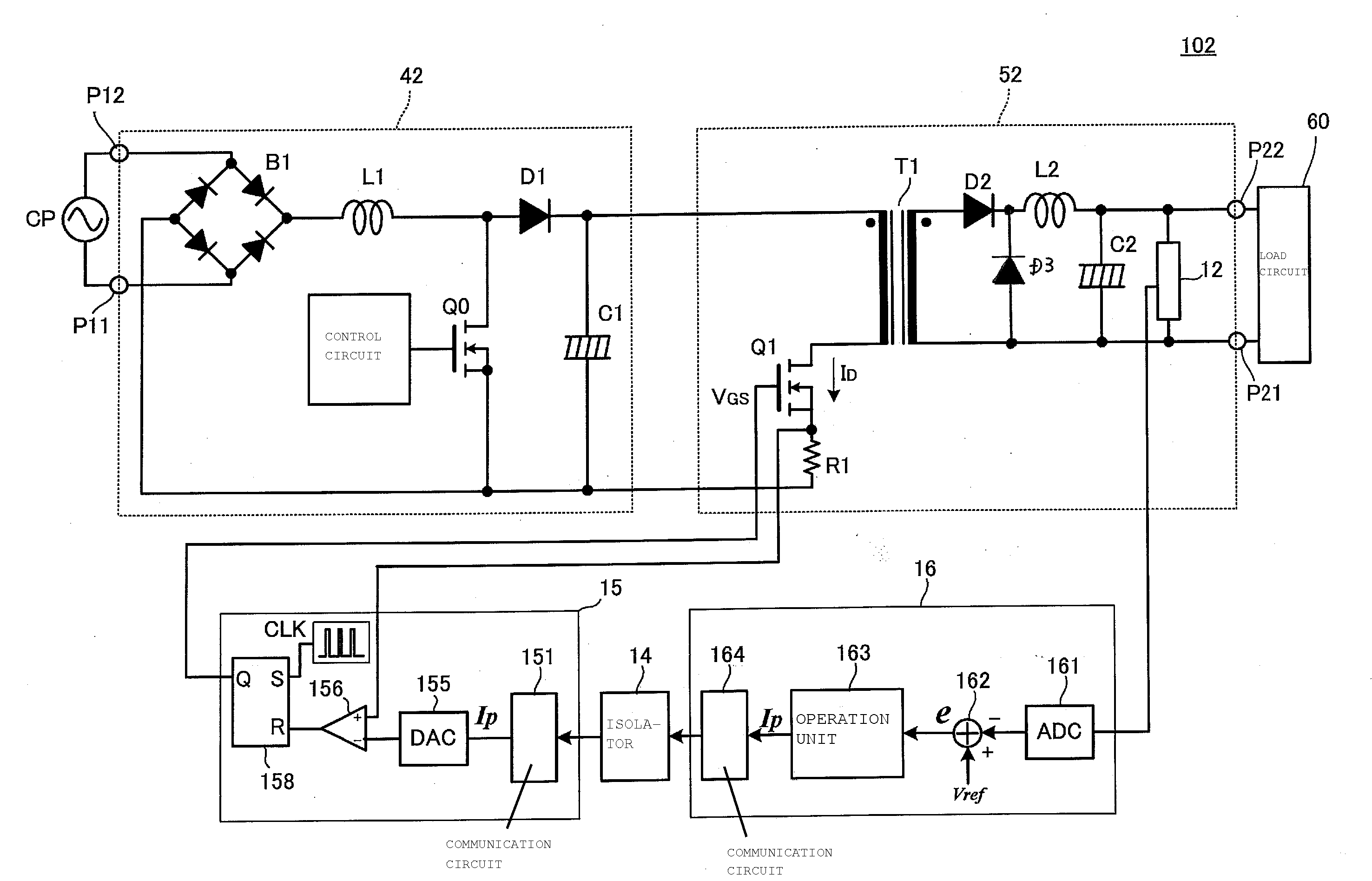
[0047]FIG. 5 is a circuit diagram of a switching power supply apparatus 102 according to a second preferred embodiment of the present invention. The switching power supply apparatus 102 includes a PFC converter 42, a DC-DC converter 52, and a primary-side digital control circuit 15, and a secondary-side digital control circuit 16. The primary-side and secondary-side digital control circuits control the PFC converter 42 and the DC-DC converter 52.
[0048]A commercial power supply CP is connected to voltage input units P11 and P12 of the switching power supply apparatus 102. A load 60 is connected to voltage output units P21 and P22 of the switching power supply apparatus 102.
[0049]A diode bridge B1, an inductor L1, a switching element Q0, and a diode D1 define a rectifying switching circuit. A capacitor C1 defines a smoothing circuit that smoothes an output of the rectifying switching circuit. The rectifying switching circuit and the smoothing circuit define the PFC converter 42.
[0050]...
third preferred embodiment
[0060]FIG. 7 is a circuit diagram of a switching power supply apparatus 103 according to a third preferred embodiment of the present invention. The switching power supply apparatus 103 includes a PFC converter 43, a DC-DC converter 53, and a primary-side digital control circuit 15, and a secondary-side digital control circuit 16. The primary-side and secondary-side digital control circuits control the PFC converter 43 and the DC-DC converter 53.
[0061]A commercial power supply CP is connected to voltage input units P11 and P12 of the switching power supply apparatus 103. A load 60 is connected to voltage output units P21 and P22 of the switching power supply apparatus 103.
[0062]A resistor R0 for inductor current detection is connected to the switching element Q0. A diode bridge B1, an inductor L1, a switching element Q0, a diode D1, and a capacitor C1 form the PFC converter 43.
[0063]A switching element Q1 defining a switching circuit is connected in series with the primary winding of...
PUM
 Abstract
Description
Claims
Application Information