
Ratchet wrench

Active Publication Date: 2011-08-18
HUANG PING CHUNG
View PDF5 Cites 5 Cited by
  • Summary
  • Abstract
  • Description
  • Claims
  • Application Information

AI Technical Summary

Benefits of technology

[0010]Therefore, it is a primary objective of the present invention to overcome the aforementioned shortcoming and deficiency of the prior art by providing a ratchet wrench composed of a fixed jaw, a moving jaw, a ratchet and an elastic element, and having a structure much simpler than the conventional ratchet wrenches, and the simple structure comes with less components and allows users to operate the ratchet wrench in a special space, such as a pipeline.
[0011]A secondary objective of the present invention is to install a ratchet between a moving jaw and a fixed jaw, wherein the moving jaw has a clamp for latching teeth of the ratchet, and an elastic element is provided for supporting and propping the moving jaw, such that the ratchet can be rotated in a direction with respect to the handle and the jaw, and the wrench can achieve the effects of an idle rotation and a reciprocal operation.
[0012]A tertiary objective of the present invention is to design the radius of curvature of the external circumference of the ratchet to be smaller than the radius of curvature of the clamp of the moving jaw in order to engage the teeth of the ratchet with the teeth of the moving jaw, and the tooth pitch of the ratchet to be smaller than the tooth pitch of the moving jaw in order to enhance the strength of the teeth of the moving jaw. In addition, the elastic element is provided for pressing the teeth of the moving jaw against the teeth of the ratchet, such that the ratchet can be rotated in a direction with respect to the handle and the two jaws.
[0013]A quaternary objective of the present invention is to provide a larger angle for pivotally turning the moving jaw, such that a larger opening can be provided between the moving jaw and the fixed jaw to facilitate the removal, replacement or maintenance of the ratchet between the two jaws.

Problems solved by technology

Although the closed ratchet wrench can use the ratchet 61 with more teeth around its external circumference to rotate with a smaller angle reciprocally, users have to sheathe the ratchet 61 vertically around the external periphery of a workpiece, but cannot sheathe the ratchet 61 sideway to the external periphery of the workpiece, so that such ratchet wrench cannot be operated in a special space such as a nut installed onto a pipeline, and thus giving rise to an inconvenient operation.

Method used


Image

  • Ratchet wrench
  • Ratchet wrench
  • Ratchet wrench

Examples


Embodiment Construction

[0029]The technical characteristics of the present invention will become apparent with the detailed description of the preferred embodiments and the illustration of the related drawings.

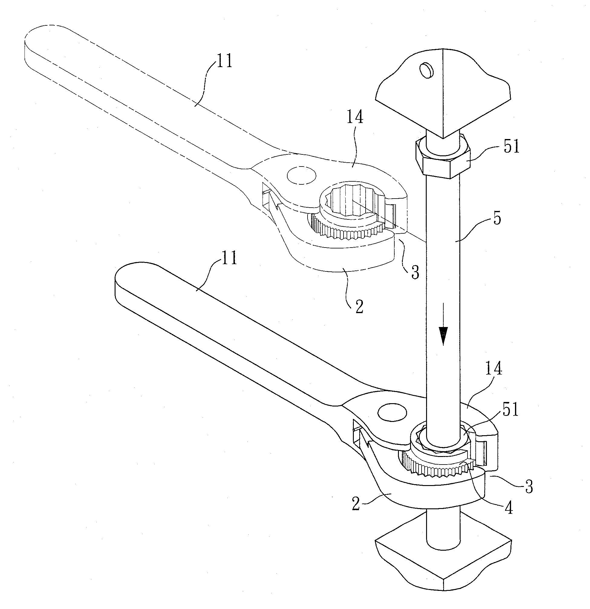
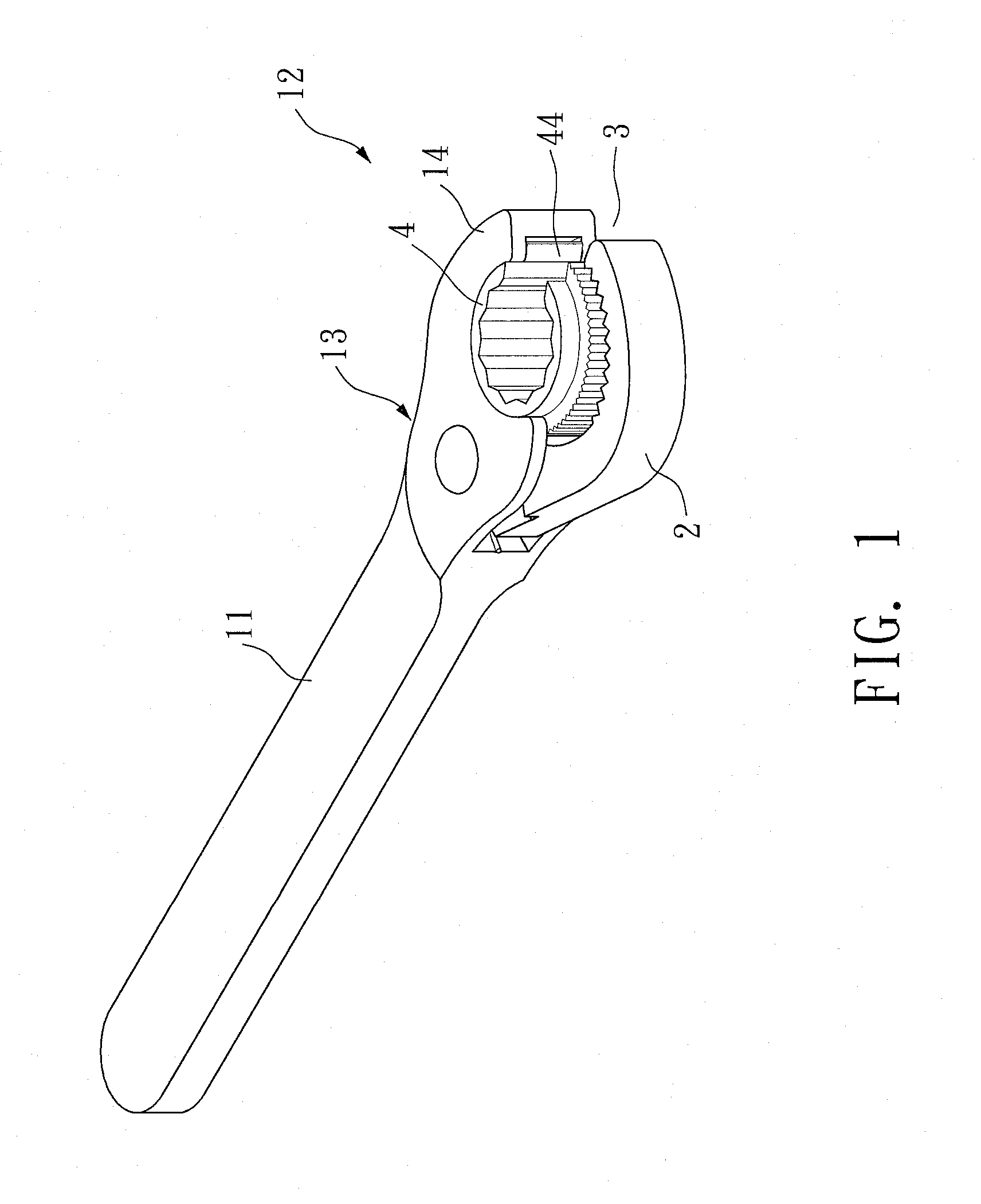
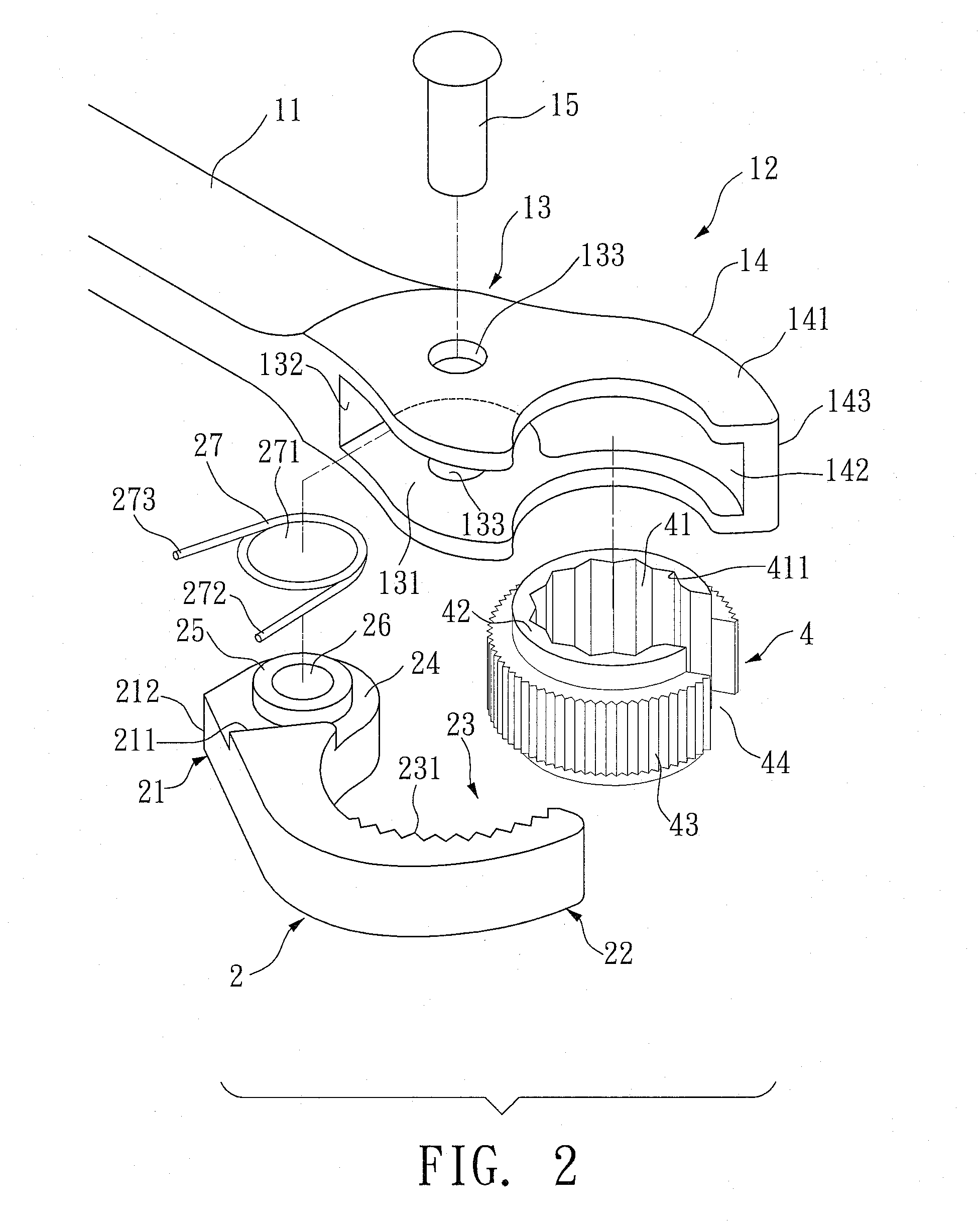
[0030]With reference to FIGS. 1 to 6 for preferred embodiments of a ratchet wrench in accordance with the present invention, the preferred embodiments are provided for the purpose of demonstrating the present invention only, but not intended for limiting the scope of the invention.

[0031]The ratchet wrench in accordance with a first preferred embodiment of the present invention comprises:

[0032]a handle 11, having a working end 12, a pivot portion 13 formed at the working end 12 and a fixed jaw 14 in an arc shape and integrally extended from the working end 12, wherein the pivot portion 13 has a containing space 131 formed at an internal side of the pivot portion 13, and the containing space 131 has a bottom edge 132, and the pivot portion 13 has two axle holes 133 formed on both lateral sides of the c...


PUM


Abstract

A ratchet wrench includes a handle and a moving jaw. The handle has a pivot portion disposed at a working end of the handle and a fixed jaw integrally extended from the handle. The moving jaw has a pivoting base pivotally coupled to the pivot portion, and a ratchet is installed between the two jaws, and the moving jaw further has a clamp, and the clamp has a plurality of continuously arranged teeth, and the handle has an elastic element for propping the moving jaw, such that the moving jaw can be abutted against the ratchet, and the teeth of the moving jaw are engaged with the teeth of the ratchet.

Description

BACKGROUND OF THE INVENTION[0001]1. Field of the Invention[0002]The present invention relates to a ratchet wrench, and more particularly to a ratchet wrench having a structure of simple components and featuring a convenient application.[0003]2. Description of the Related Art[0004]With reference to FIG. 7 for a conventional closed ratchet wrench, the wrench includes a closed ratchet 61 having a hole 62 for sheathing a screw element such as a bolt or a nut, a latch element 64 installed in a slot 63 of the wrench and engaged with the ratchet 61, an elastic element 65 for supporting and propping the latch element 64 to control the ratchet 61 to be rotated in a direction repeatedly.[0005]With reference to FIG. 8 for another conventional opening ratchet wrench, the wrench includes a C-shaped jaw 71, a non-closed ratchet 72 contained in the jaw 71, and a latch element 73 included between the jaw 71 and the ratchet 72 and an elastic element 74, wherein the latch element 73 is propped and pu...

Claims


Application Information

Patent Timeline
IPC IPC(8): B25B13/46B25B13/48
CPCB25B13/08B25B13/48B25B13/463
Inventor HUANG, PING-CHUNG
Owner HUANG PING CHUNG
Learn More