
Laser collimating module

Active Publication Date: 2021-04-08
ARIMA LASERS CORP
View PDF0 Cites 0 Cited by
  • Summary
  • Abstract
  • Description
  • Claims
  • Application Information

AI Technical Summary

Benefits of technology

The present invention provides a laser collimating module with a unique design that eliminates the need for a focusing lens. This reduces the number of components and makes the module more compact. The module includes a heat dissipating base, a laser diode chip, a cylindrical lens, and an opening. The laser diode chip is positioned on the fixing element of the heat dissipating base, and the cylindrical lens is placed in the space between the laser diode chip and the opening. The cylindrical lens has a narrowed light emitting angle, resulting in a collimated beam of laser light. The cap of the module has a flat surface and a circular opening for fixing the cylindrical lens using adhesives. Overall, this design simplifies the assembly process and reduces the size of the laser collimating module.

Problems solved by technology

Furthermore, the laser adjusting assembly 10 needs quite an amount of components for assembly, and a huge volume is unavoidable due to the distances required between the components within the assembly.

Method used


Image

  • Laser collimating module
  • Laser collimating module
  • Laser collimating module

Examples


Embodiment Construction

[0024]Referring to FIGS. 2A-6, in a preferred embodiment, a laser collimating module 20 includes a heat dissipating base 21, a laser diode chip 22, a cap 23 and a cylindrical lens 24.

[0025]The heat dissipating base 21 has a fixing element 211 on a top thereof and a plurality of pins 212 at a bottom thereof.

[0026]The laser diode chip 22 is disposed on the fixing element 211 of the heat dissipating base 21.

[0027]The cap 23 is covering on the heat dissipating base 21 and has a placing space 231 therein and an opening 232 on a top thereof. The opening 232 is arranged above the placing space 231 and connecting thereto, correspondingly aligning with the laser diode chip 22.

[0028]The cylindrical lens 24 is disposed in the placing space 231 and has a first surface 241 facing toward the laser diode chip 22 with a first minimized distance D1 arranged therebetween and a second surface 242 facing toward the opening 232 with a second minimized distance D2 arranged therebetween. In this embodimen...


PUM


Abstract

A laser collimating module includes a heat dissipating base having a fixing element on a top thereof and a plurality of pins at a bottom thereof, a laser diode chip disposed on the fixing element, a cap covering on the heat dissipating base with a placing space therein and an opening on a top thereof, and a cylindrical lens disposed in the placing space. The opening of the cap is connecting to the placing space and aligning with the laser diode chip correspondingly. The cylindrical lens has a first surface facing toward the laser diode chip with a first minimized distance arranged therebetween and a second surface facing toward the opening with a second minimized distance arranged therebetween. The laser diode chip is stimulated and emits an elliptical laser beam, and a light emitting angle is formed. As the elliptical laser beam passes through the cylindrical lens, the light emitting angle is narrowed and the laser beam is collimated to be a linear beam.

Description

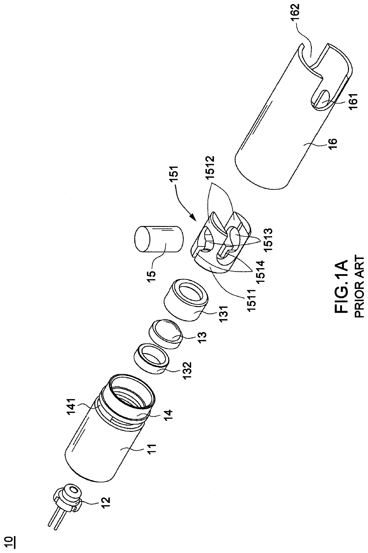
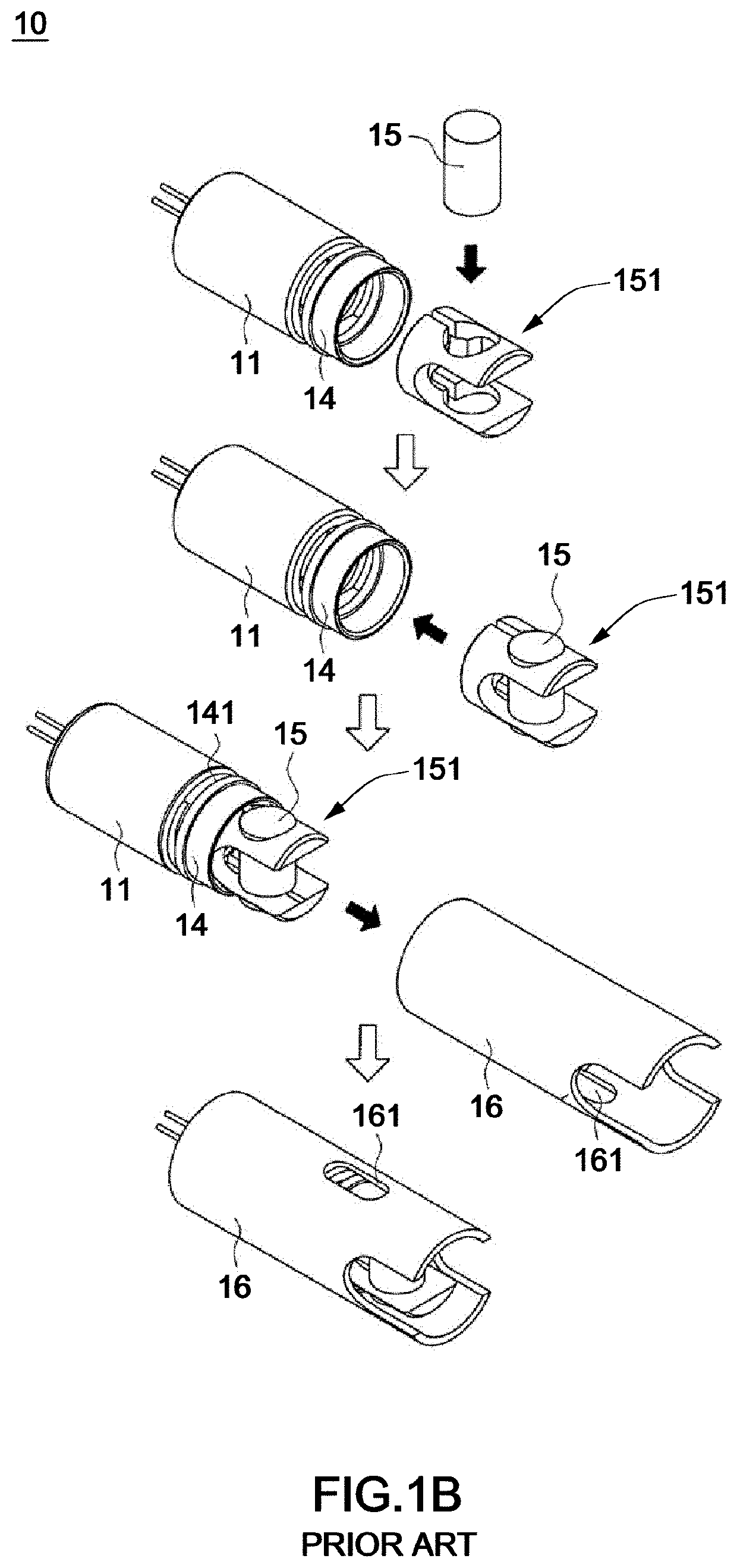
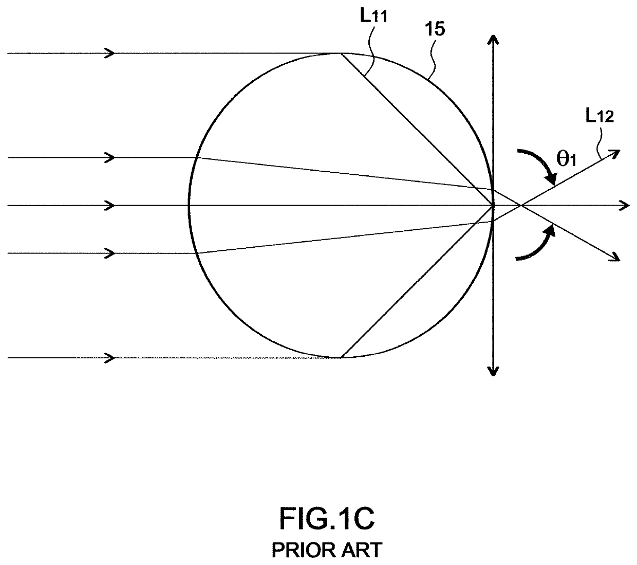
BACKGROUND OF THE INVENTION1. Field of the Invention[0001]The invention relates to a laser module, particularly to one that collimates laser beams with a miniature volume.2. Description of the Related Art[0002]Referring to FIGS. 1A and 1B, a laser adjusting assembly 10 is disclosed in Taiwanese patent No. 1364148. As shown in FIG. 1A, the laser adjusting assembly 10 includes a hollow column 11, a laser diode 12 disposed at an end of the hollow column 11 therein, a focusing lens 13 disposed inside the hollow column 11 at a front of the laser diode 12 and fixed by a seat 131 and a fixing ring 132 inside the hollow column 11, an adjusting ring 14 engaging another end of the hollow column 11 and having a reference section 141, a cylindrical lens 15 engaging in a fixing element 151 and further engaging the adjusting ring 14 and fixed thereby and an external tube 16 engaging and fixing the adjusting ring 14 and the hollow column 11. The fixing element 151 includes a hollow section 1511 an...

Claims


Application Information

Patent Timeline
IPC IPC(8): H01S5/022H01S5/024G02B27/30G02B27/09G02B7/02
CPCH01S5/02288H01S5/02212H01S5/02469G02B7/025G02B27/0916G02B27/0966G02B27/0927G02B27/30H01S5/02253G02B19/0052G02B19/0014
Inventor TSENG, CHENG-TSUNGFANG, MING-HUI
Owner ARIMA LASERS CORP
Learn More