
Work recovery system for a gas turbine engine utilizing an overexpanded, recuperated supercritical co2 cycle driven by cooled cooling air waste heat

a gas turbine engine and waste heat recovery technology, which is applied in steam engine plants, machines/engines, mechanical equipment, etc., can solve problems such as the rise in the gas temperature at the compressor exi

Inactive Publication Date: 2020-07-16
RAYTHEON TECH CORP
View PDF0 Cites 2 Cited by
  • Summary
  • Abstract
  • Description
  • Claims
  • Application Information

AI Technical Summary

Benefits of technology

This patent describes a method for recovering heat from a gas turbine engine. The method involves using a specific type of fluid called sCO2, which is heated by the engine and then compressed. The compressed fluid is then cooled and sent back to the engine to recover heat. The technical effect of this method is that it allows for more efficient recovery of heat from the engine, which can lead to improved efficiency and performance.

Problems solved by technology

The compression process of the gas turbine engine results in a rise in the temperature of the gas at the compressor exit due to increasing pressure and component inefficiencies.

Method used


Image

  • Work recovery system for a gas turbine engine utilizing an overexpanded, recuperated supercritical co2 cycle driven by cooled cooling air waste heat
  • Work recovery system for a gas turbine engine utilizing an overexpanded, recuperated supercritical co2 cycle driven by cooled cooling air waste heat

Examples


Embodiment Construction

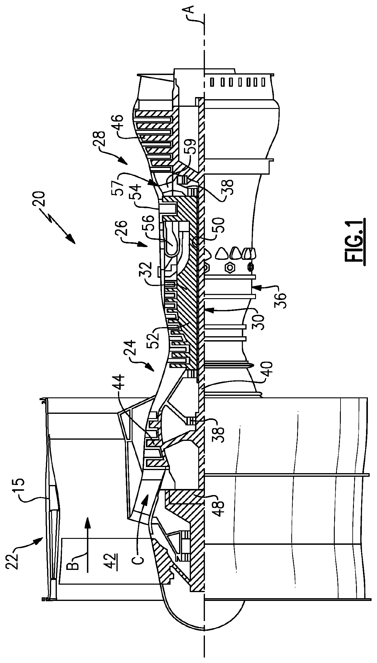
[0028]FIG. 1 schematically illustrates a gas turbine engine 20. The gas turbine engine 20 is disclosed herein as a two-spool turbofan that generally incorporates a fan section 22, a compressor section 24, a combustor section 26 and a turbine section 28. Alternative engines might include an augmentor section (not shown) among other systems or features. The fan section 22 drives air along a bypass flow path B in a bypass duct defined within a nacelle 15, and also drives air along a core flow path C for compression and communication into the combustor section 26 then expansion through the turbine section 28. Although depicted as a two-spool turbofan gas turbine engine in the disclosed non-limiting embodiment, it should be understood that the concepts described herein are not limited to use with two-spool turbofans as the teachings may be applied to other types of turbine engines including single spool or three-spool architectures.

[0029]The exemplary engine 20 generally includes a low s...


PUM


Abstract

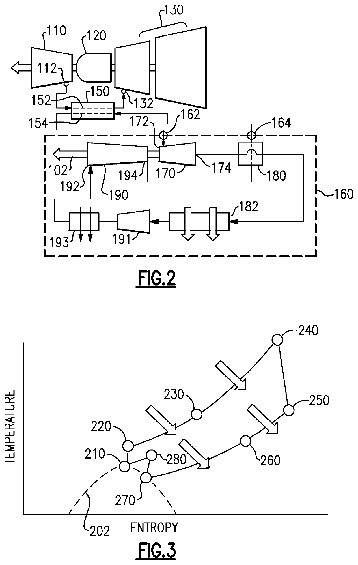
A gas turbine engine includes a primary flowpath fluidly connecting a compressor section, a combustor section, and a turbine section. A heat exchanger includes an first inlet connected to a high pressure compressor bleed, a first outlet connected to a high pressure turbine inlet. The heat exchanger further includes a second inlet fluidly connected to a supercharged CO2 (sCO2) work recovery cycle and a second outlet connected to the sCO2 work recovery cycle. The sCO2 work recovery cycle is an overexpanded, recuperated work recovery cycle.

Description

TECHNICAL FIELD[0001]The present disclosure relates generally to a system for recovering waste heat in a gas turbine engine, and more specifically to a work recovery system utilizing a supercritical CO2 cycle to recover work from excess heat.BACKGROUND[0002]Gas turbine engines, such as those utilized in commercial and military aircraft, include a compressor section that compresses air, a combustor section in which the compressed air is mixed with a fuel and ignited, and a turbine section across which the resultant combustion products are expanded. The expansion of the combustion products drives the turbine section to rotate. As the turbine section is connected to the compressor section via a shaft, the rotation of the turbine section further drives the compressor section to rotate. In some examples, a fan is also connected to the shaft and is driven to rotate via rotation of the turbine as well.[0003]The compression process of the gas turbine engine results in a rise in the temperat...

Claims


Application Information

Patent Timeline
IPC IPC(8): F01K23/02F02C3/073F02C6/06F02C6/18F01K25/10
CPCF05D2220/32F02C3/073F05D2220/62F05D2260/234F01K23/02F02C6/18F02C6/06F01K25/103F05D2220/74F05D2260/213F05D2210/12F05D2220/50F02C6/08F02C1/10
Inventor MCAULIFFE, BRENDAN T.STAUBACH, JOSEPH B.SOMANATH, NAGENDRA
Owner RAYTHEON TECH CORP
Learn More