Phase change cooling device and control method

Pending Publication Date: 2020-07-16
NEC CORP
View PDF0 Cites 0 Cited by
  • Summary
  • Abstract
  • Description
  • Claims
  • Application Information

AI Technical Summary

Benefits of technology

[0015]The present invention is able to achieve stable high-effic

Problems solved by technology

However, as an amount of information-processing increases in a data center, an amount of power consumption also increases in the data center.
However, as an amount of information-processing increases, such an air conditioner also requires huge power.
Therefore, in order to re

Method used


Image

  • Phase change cooling device and control method
  • Phase change cooling device and control method
  • Phase change cooling device and control method

Examples


first example embodiment

[0031]First, a phase change cooling device and a control method according to a first example embodiment of the present invention will be described.

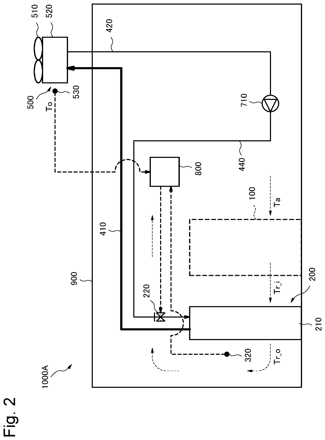
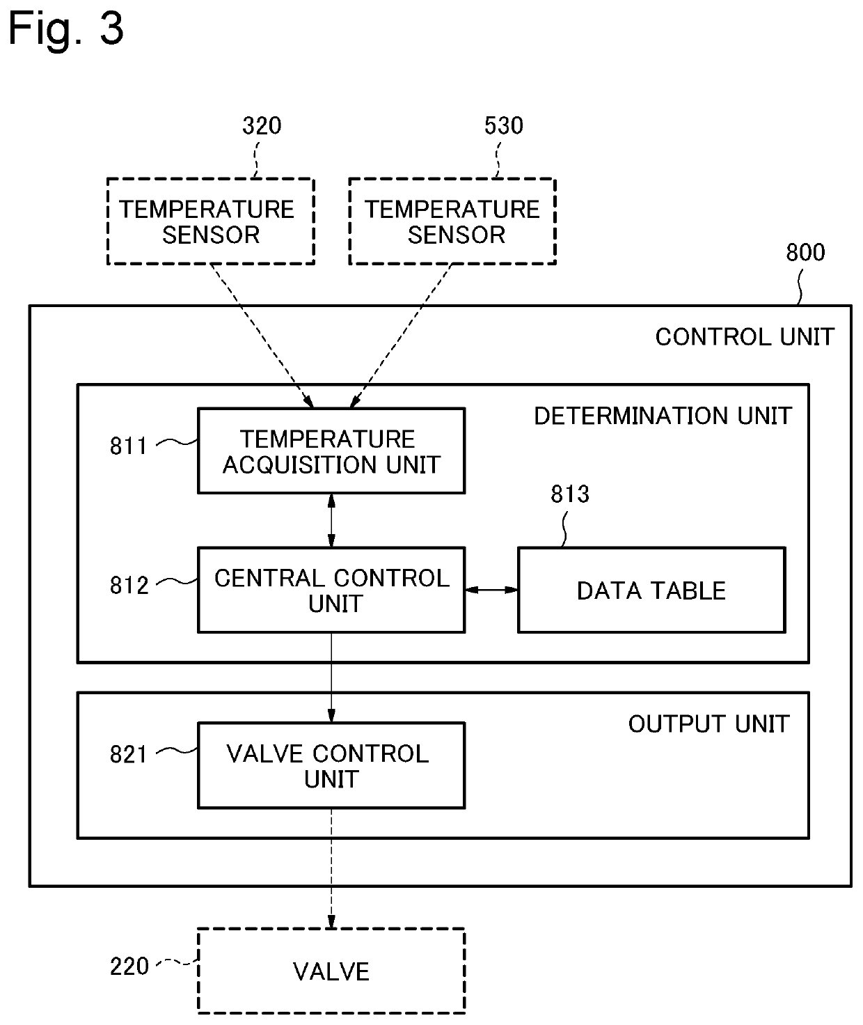
[0032]FIG. 2 is a configuration diagram of a phase change cooling device 1000A according to the first example embodiment of the present invention. FIG. 3 is a configuration diagram of a control unit 800 in FIG. 2. FIG. 4 is a flowchart for determining a valve opening degree according to the first example embodiment. FIG. 5 is a flowchart for describing a flow of step S120 in FIG. 4 in more detail. FIGS. 6A and 6B are configuration diagrams of data tables.

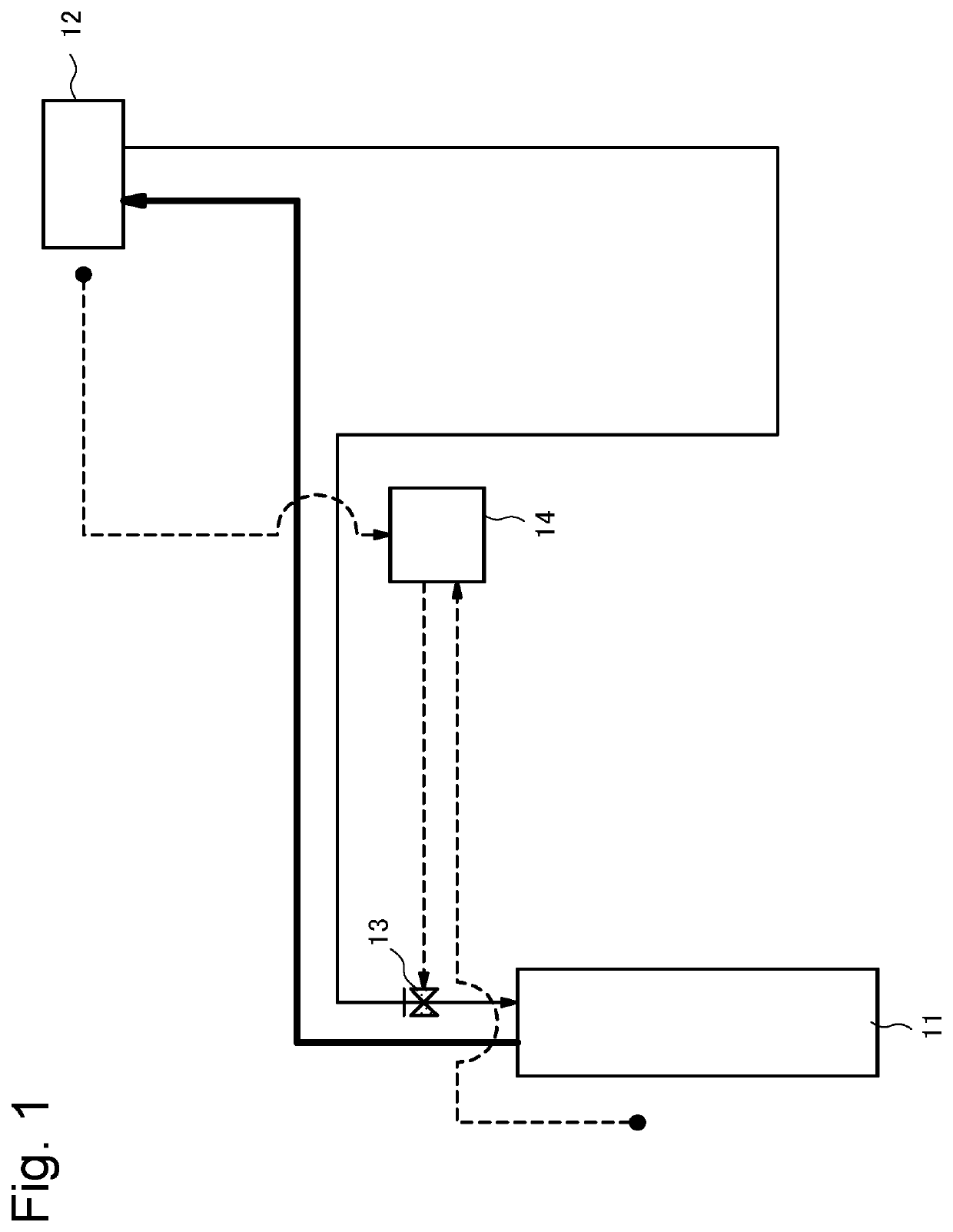
[0033]The phase change cooling device 1000A in FIG. 2 transports heat and radiates heat between a heat receiver 210 of a local cooler 200 and outdoor equipment 500 by virtue of a cycle of gasifying and condensing a coolant. A housing 900 of the phase change cooling device 1000A in FIG. 2 is disposed with a plurality of heat receivers 210 in which a coolant boils by receiving exhaust heat ...

second example embodiment

[0053]Next, a phase change cooling device and a control method according to a second example embodiment of the present invention will be described. FIG. 7 is a configuration diagram of the phase change cooling device according to the second example embodiment. A configuration similar to that of the phase change cooling device 1000A according to the first example embodiment is attached with a reference numeral identical with that of the phase change cooling device 1000A, and detailed description thereof is omitted.

[0054]A phase change cooling device 1000B in FIG. 7 transports heat and radiates heat between a heat receiver 210 of a local cooler 200 and outdoor equipment 500 by virtue of a cycle of gasifying and condensing a coolant. The phase change cooling device 1000E in FIG. 7 has a configuration similar to that of the phase change cooling device 1000A according to the first example embodiment, with an addition of a rack intake air temperature sensor 300 and a rack exhaust air temp...

third example embodiment

[0058]Next, a phase change cooling device and a control method according to a third example embodiment of the present invention will be described. FIG. 8 is a configuration diagram of the phase change cooling device according to the third example embodiment. A configuration similar to that of the phase change cooling device 1000B according to the second example embodiment is attached with a reference numeral identical with that of the phase change cooling device 1000B, and detailed description thereof is omitted.

[0059]A phase change cooling device 10000 in FIG. 8 transports heat and radiates beat between a heat receiver 210 of a local cooler 200 and outdoor equipment 500 by virtue of a cycle of gasifying and condensing a coolant. The phase change cooling device 10000 in FIG. 8 has a configuration similar to that of the phase change cooling device 10003 according to the second example embodiment, with an addition of a reserve tank 610. The reserve tank 610 is disposed in a middle of ...


PUM


Abstract

Provided are a phase change cooling device and a control method, whereby stable high-efficiency cooling performance can be obtained according to heat exchange performance. This phase change cooling device includes: a heat receiver which accommodates a coolant and receives heat from a heat generation body which is to be cooled; a heat radiator which radiates the heat of a coolant vapor of the coolant gasified by receiving heat by means of the heat receiver, and recirculates a liquefied liquid coolant to the heat receiver; a valve for controlling the flow rate of the liquid coolant; and a control means for controlling the opening degree of the valve, wherein the control means controls the opening degree of the valve on the basis of an exhaust temperature, which is the temperature after being discharged from the heat receiver, and the temperature in the vicinity of the heat radiator.

Description

TECHNICAL FIELD[0001]The present invention relates to a phase change cooling device and a control method, particularly, to a phase change cooling device and a control method for transporting heat and radiating heat by virtue of a cycle of gasifying and condensing a coolant.BACKGROUND ART[0002]As a cloud service develops in recent years, an amount of required information-processing is continuously increasing. In order to process huge data, a data center that enhances energy efficiency by concentrating servers and pieces of network equipment at one place has been operating in various places. However, as an amount of information-processing increases in a data center, an amount of power consumption also increases in the data center.[0003]In the data center, pieces of electronic equipment such as a central processing unit (CPU) and a large scale integration (LSI) are accommodated. These pieces of electronic equipment generate heat, and thus an air conditioner is used for maintaining an a...

Claims


Application Information

Patent Timeline
IPC IPC(8): F28F27/02F25B19/00
CPCF28F2250/08F25B19/00F28F27/02H05K7/20F28D15/06G06F1/20F28D15/0266F25B23/006
Inventor SATO, MASANORITODOROKI, KOICHIMATSUNAGA, ARIHIROWADA, MIZUKIYOSHIKAWA, MINORU
Owner NEC CORP
Why Eureka
Try Eureka