Passive heat dissipation evaporator and passive heat dissipation system

A passive, evaporator technology, applied in the direction of cooling/ventilation/heating transformation, etc., can solve the problems of loose contact between capillary core and evaporator, reduce capillary core permeability, gap in heat dissipation capacity, etc., to improve boiling limit and critical heat flow Density, conflict avoidance, small size effects

Pending Publication Date: 2022-07-29
山东高等技术研究院
View PDF0 Cites 0 Cited by
  • Summary
  • Abstract
  • Description
  • Claims
  • Application Information

AI Technical Summary

Problems solved by technology

However, the inventors found that due to the shortcomings of low permeability, loose contact between capillary wick and evaporator, and low boiling limit, the heat dissipation capacity of loop heat pipe still has a significant gap compared with active heat dissipation technology. Thick, not conducive to the arrangement in a narrow space
These problems limit the application of loop heat pipes in the cooling of microelectronic devices
[0006] Moreover, the inventors have also found that capillary pressure and permeability are key parameters of heat exchange equipment driven by capillary force, which determine the capillary limit and heat transfer limit in the case of high heat flux or anti-gravity. In passive heat dissipation technology, usually Achieved by reducing the pore size of the capillary core, which greatly reduces the permeability of the capillary core, which in turn reduces the heat dissipation performance

Method used


Image

  • Passive heat dissipation evaporator and passive heat dissipation system
  • Passive heat dissipation evaporator and passive heat dissipation system
  • Passive heat dissipation evaporator and passive heat dissipation system

Examples


Embodiment 1

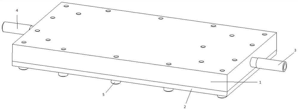
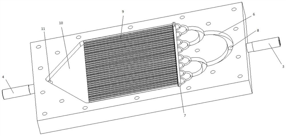
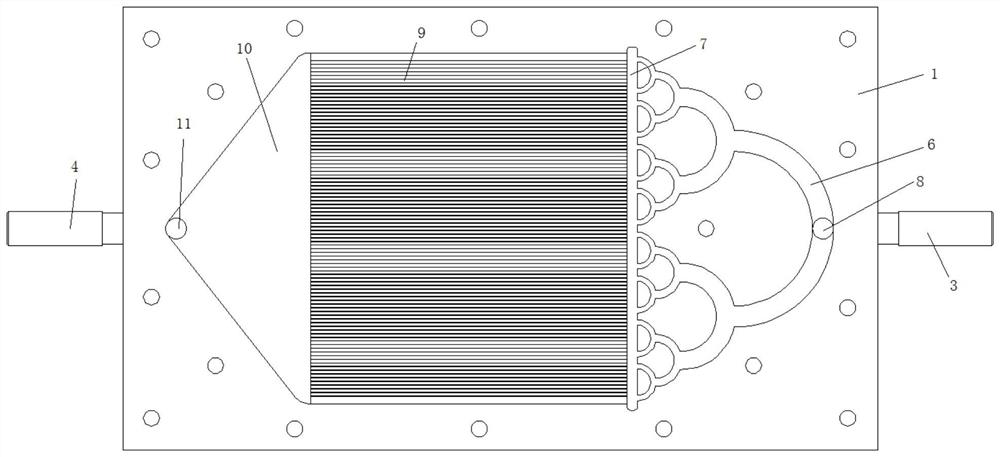
[0036] This embodiment provides a passive heat dissipation evaporator, such as Figure 1-3 As shown, it includes a plate body, which is made of heat-conducting material. The plate body in this embodiment is made of copper material, which improves the heat-conducting capacity of the entire evaporator, and adopts a flat-plate structure, which is convenient for direct installation on electronic components. device or chip surface.

[0037] The plate body is assembled by the first plate part 1 and the second plate part 2, the lower surface of the first plate part is attached to the upper surface of the second plate part, and the first plate part and the second plate part are connected by a plurality of fixing bolts The whole constitutes the entire board body.

[0038] When the first plate part 1 and the second plate part 2 are connected, a sealant is applied between the first plate part 1 and the second plate part 2 to prevent the leakage of the cooling medium.

[0039] The lower...

Embodiment 2

[0059] This embodiment provides a passive cooling system, such as Figure 4 As shown, the passive heat dissipation evaporator described in Embodiment 1 is provided.

[0060] Specifically, the second inlet channel of the passive heat dissipation evaporator is connected to the outlet of the compensation chamber 13 through the liquid phase pipeline 12, the inlet of the compensation chamber 13 is connected to the outlet of the condenser 14 through the pipeline, and the inlet of the condenser 14 is connected through the gas phase pipeline. 15 is connected to the second flow channel part of the passive heat dissipation evaporator.

[0061] The installation height of the compensation chamber 13 is higher than that of the passive heat dissipation evaporator, and the installation height of the condenser 14 is higher than that of the compensation chamber 13 .

[0062] In this embodiment, as Figure 5-Figure 6 As shown, the compensation chamber 13 can adopt the structure of the compens...


PUM


Abstract

The passive heat dissipation evaporator comprises a plate body made of a heat conduction material, a steam backflow prevention flow channel, an evaporation flow channel and an outlet flow channel are sequentially arranged in the plate body in the flowing direction of a cooling working medium, the evaporation flow channel comprises a plurality of layers of micron-sized capillary flow channels, one end of each micron-sized capillary flow channel communicates with a confluence cavity, and the other end of each micron-sized capillary flow channel communicates with an outlet flow channel. The flow converging cavity is communicated with the steam backflow preventing flow channel, the other end of the micron-sized capillary flow channel is communicated with the outlet flow channel, and the evaporator is good in heat dissipation effect and suitable for being used in a narrow space.

Description

technical field [0001] The invention relates to the technical field of heat dissipation of electronic components, in particular to a passive heat dissipation evaporator and a passive heat dissipation system. Background technique [0002] The statements herein merely provide background related to the present invention and do not necessarily constitute prior art. [0003] With the rapid development of microelectronics technology, the high heat flux density generated by electronic devices during operation has become a key factor affecting the reliability and service life of devices. How to efficiently dissipate the extremely high heat production per unit area has become one of the key issues restricting the development of microelectronic devices. [0004] According to whether there is an external circulation power device, the current cooling technology can be divided into two categories: active and passive. Pump-driven micro-channel cooling technology is one of the important ...

Claims


Application Information

Patent Timeline
Patent Type & Authority Applications(China)
IPC IPC(8): H05K7/20
CPCH05K7/20309H05K7/20318
Inventor 马晓腾梁嵩林崔峥张廉齐龚晗
Owner 山东高等技术研究院
Why Eureka
Try Eureka