Soaking plate and manufacturing and application method thereof

A technology of soaking plate and shell plate, applied in the field of heat dissipation, can solve the problems such as insufficient contact of the liquid absorbing core, reduction of working fluid return channels, reduction of capillary limit and boiling limit, etc.

Pending Publication Date: 2017-06-06
刘康
View PDF15 Cites 14 Cited by
  • Summary
  • Abstract
  • Description
  • Claims
  • Application Information

AI Technical Summary

Problems solved by technology

(2) In view of the defects of the existing vapor chambers that the contact between the various parts of the liquid-absorbing cores is not close enough or too close due to the manufacturing process, which eventually leads to the reduction

Method used


Image

  • Soaking plate and manufacturing and application method thereof
  • Soaking plate and manufacturing and application method thereof
  • Soaking plate and manufacturing and application method thereof

Examples


Embodiment 1

[0078] Embodiment one includes inventions one and two.

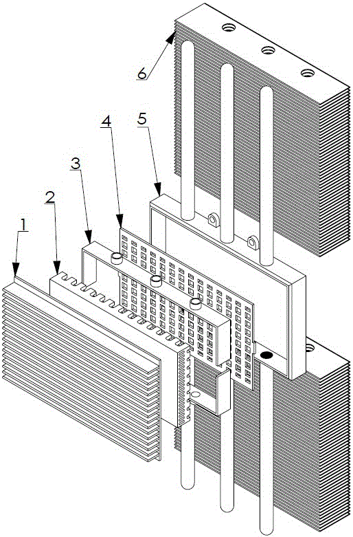
[0079] Such as figure 1 As shown in —14, Invention 2 is formed by combining Invention 1 with the second heat dissipation fin 6. The second heat dissipation fin 6 is made of aluminum metal sheet, and the edge of the metal profile can be formed into a streamlined edge structure 62 by grinding and other processes. , and then blanking, punching, forming holes 61, and finally combining a number of second heat dissipation fins through the buckle fin process.

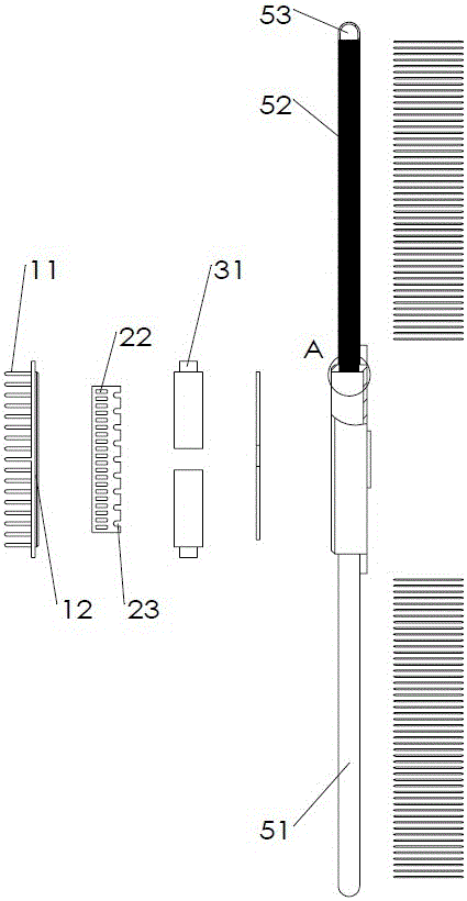
[0080] Invention 1 consists of an upper shell plate 1, a first capillary structure 2, a third capillary structure 3, a second capillary structure 4, and a lower shell plate 5, forming a closed vacuum chamber containing an appropriate amount of working fluid (not shown).

[0081] The upper shell 1 can obtain the first heat dissipation fins 11 and the boss 12 of the upper shell by using an aluminum extrusion process.

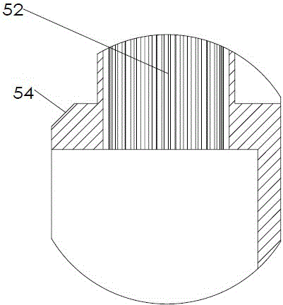
[0082] The main part of the lower shell 5 can be ma...

Embodiment 2

[0090] Embodiment 2 includes invention 3.

[0091] Input the shape, size, and material of inventions 1 and 2 into the computer, and manufacture them through a 3D printer, or set the first, second, and third capillary structures in the already-made lower shell plate 5 through a 3D printer, and then pass through the remaining The next step is to complete the production. It can also be manufactured in a vacuum environment to obtain related products without welds.

Embodiment 3

[0092] Embodiment three includes inventions four and five.

[0093] Such as Figure 15 As shown, the liquid metal 105 is sealed between the PCB board 104 , the chip 103 , the o-ring 102 , and the heat sink 101 . The o-ring 102 has the function of reducing the pressure between the heat sink 101 and the chip 103, and the function of reducing mechanical vibration, and preventing the entry of external air and foreign objects.


PUM

PropertyMeasurementUnit
Thicknessaaaaaaaaaa

Abstract

The invention relates to the field of heat dissipation, in particular to a soaking plate and a manufacturing and application method thereof. Heat generated by a heat source can be transferred to an external environment through a radiator more quickly to lower the working temperature of the heat source, so that the heat source can be operated more safely, efficiently, stably and enduringly, in particular for a graphics card with high heating quantity and a chip of a calculation accelerating card. The soaking plate enhances the efficiency of a liquid sucking core, can suck more working mediums, enables the working mediums to flow back smoothly, and meanwhile, improves the overall structural intensity of the liquid sucking core and the socking plate to prevent deformation of the soaking plate; the soaking plate greatly improves the heat dissipating performance through more condensers extending from the side surface, and is provided with a sealing piece mounting structure at the bottom for matching with a sealing piece to use; and as the heat can be transferred from the heat source to the radiator through liquid-state metal, when the use efficiency of the radiator is improved, the harm caused by leakage of the liquid-state metal is prevented, and the protecting effect on the heat source and the radiator is achieved.

Description

technical field [0001] The invention relates to the field of heat dissipation, in particular to a vapor chamber and methods for manufacturing and using the same. Background technique [0002] The heat pipe is a heat transfer element invented by G.M.Grover of the Los Alamos National Laboratory in the United States in 1963. It makes full use of the principle of heat conduction and the phase change heat transfer properties of the working fluid, and quickly transfers the heat of the heating object to the heat source through the heat pipe. Its ability to conduct heat exceeds that of any known metal. Heat pipe technology was widely used in aerospace, military and other industries before. Since it was introduced into the radiator manufacturing industry, people have changed the traditional radiator design ideas and opened up a new world of heat dissipation industry. It is now common on the radiators of cpu and gpu. Document 1 (National Standard of the People's Republic of China GB...

Claims


Application Information

Patent Timeline
IPC IPC(8): F28D15/04
CPCF28D15/0283F28D15/046
Inventor 刘康
Owner 刘康
Why Eureka
Try Eureka