Flight control surface for an aircraft and method for manufacturing said flight control surface

Pending Publication Date: 2020-07-23
AIRBUS OPERATIONS SL
View PDF6 Cites 1 Cited by
  • Summary
  • Abstract
  • Description
  • Claims
  • Application Information

AI Technical Summary

Benefits of technology

[0011]According to the above, the claimed invention allows the suppression of the aerodynamic filler described in the state of the art by covering the whole trailing edge gap with a U-shaped profile with a decreasing section, usually made from aluminum. The decreasing section also avoids the need of a filler located in between the U-shaped profile for performing the stamping tasks of the rivets.
[0012]It is clear therefore that the claimed invention has the advantage that it avoids the time of application of the filler and also the subsequent curing time, both during manufacturing and maintenance.
[0013]Finally, as the U-shaped profile progressively decreases towards its end, it achieves a desir

Problems solved by technology

The application of the filler is time consuming and also increases the weight of the flight control surface.
Additionally, this filler is sensitive to being cracked in service leading to subsequent cracking and flacking of the external surface paint scheme which may fu

Method used


Image

  • Flight control surface for an aircraft and method for  manufacturing said flight control surface
  • Flight control surface for an aircraft and method for  manufacturing said flight control surface
  • Flight control surface for an aircraft and method for  manufacturing said flight control surface

Examples


Example

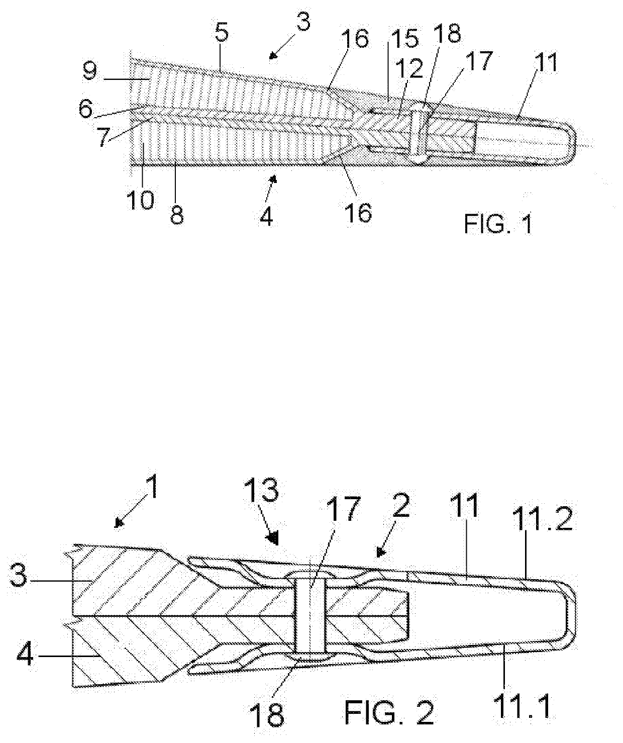
[0033]FIG. 1 discloses a control surface according to the state of the art in which the main body (1) is depicted comprising an upper cover (3) and a lower cover (4), each cover (3, 4) comprising upper and lower skins (5, 6, 7, 8) and a core member (9, 10) located between the upper and lower skins (5, 6, 7, 8) of each cover (3, 4).

[0034]Additionally, the skins (5, 6, 7, 8) of the covers (3, 4) comprise a prolongation (12) of their length over the length of the core member (9, 10) in the chordwise direction of the control surface. This prolongation (12) defines a stepped area (16) between the area of the main body (1) in which the core member (9, 10) is present and the prolongation (12) itself wherein the core member (9, 10) is missing.

[0035]FIG. 1 discloses a U-shaped profile (11) that encloses the prolongation (12) of the main body (1) and a filler material (15) filling the gap between the stepped area (16) and the U-shaped profile (11) such that a smooth transition is performed. A...


PUM

PropertyMeasurementUnit
Lengthaaaaaaaaaa
Areaaaaaaaaaaa

Abstract

A flight control surface comprising a main body comprising an upper and lower cover, upper and lower skins and a core member, a prolongation of their length over the length of the core member defining a stepped area. A trailing edge of the control surface comprises a U-shaped profile enclosing the prolongation, the U-shaped profile extending towards the main body in the chordwise direction up to the stepped area and comprising a section that progressively decreases. The trailing edge comprises a first and a second set of rivets located in the prolongation, the first set of rivets joining the upper and lower covers and the second set of rivets joining the U-shaped profile, the upper covers and the lower covers.

Description

CROSS-REFERENCES TO RELATED APPLICATIONS[0001]This application claims the benefit of the European patent application No. 19382036.2 filed on Jan. 18, 2018, the entire disclosures of which are incorporated herein by way of reference.FIELD OF THE INVENTION[0002]The invention relates to a flight control surface of an aircraft and also to a method for manufacturing the flight control surface.BACKGROUND OF THE INVENTION[0003]Known control surfaces of an aircraft comprise an upper cover and a lower cover wherein each cover comprises a sandwich carbon fiber structure having upper and lower skins and a core member located between the upper and lower skins. Additionally, the skins comprise a prolongation of their length over the length of the core member in the chordwise direction of the control surface therefore generating a step in the trailing edge area due to the non-existence of the core at the edge of the control surface. This step has a strong influence on the drag created by the aero...

Claims


Application Information

Patent Timeline
IPC IPC(8): B64C9/00B29C65/60B29L31/30
CPCB29C65/60B29L2031/3076B64C9/00B64C1/12B64C7/00B64C9/02B64F5/40Y02T50/40B64C3/26
Inventor KOBIERECKI, ROBERTMENDEZ RODRÍGUEZ, MIGUEL ÁNGELSÁNCHEZ RUIZ, JUAN ANTONIOBALSA-GONZALEZ, ALBERTO
Owner AIRBUS OPERATIONS SL
Why Eureka
Try Eureka