
Tube Connection Kit

Pending Publication Date: 2020-07-23
WITHEROW RANDY
View PDF5 Cites 0 Cited by
  • Summary
  • Abstract
  • Description
  • Claims
  • Application Information

AI Technical Summary

Benefits of technology

The present invention provides a new and improved tube connection kit for a vacuum system that allows for dynamic movements of the tubing without disassembling it. The kit is easy to assemble and disassemble and is made from materials that are economical and durable. The kit allows for quick and efficient clearing of blockages from the tubing without the need to disassemble it. The kit includes a release button that is disposed on the forward portion of the female coupler and a portion of the male coupler that can be displaced by the release button to disrupt the connection. The kit also has a release slit that allows the released material to pass through. These features offer improvements in the reliability and efficiency of vacuum systems during surgical procedures.

Problems solved by technology

Existing tubing solutions for vacuum systems for medical procedures are unsatisfactory.
They often break apart unexpectedly during use, resulting in spillage of biological fluids from the tube to the surrounding area.
This spillage puts the medical professionals at risk of exposure to blood-borne pathogens, delays the surgical procedure, and endangers the patient.
The breakage may occur as a result of rotation or twisting of a portion of the tubing with respect to another portion of the tubing, which results in torsional abnormalities that can break apart tubing connections or introduce kinks in the tubing which blocks the flow of fluid therein.
During the course of a procedure, biological fluid within the tube clots and forms blockages.
Blockage results in the need to replace one or more tubes of the vacuum system, which is time-consuming and fraught with difficulty and additional risk of exposure to blood-borne pathogens.
These items are often incompatible with the dynamic nature of a surgical theater and result in frustration and unnecessary danger due to their structural and functional shortcomings.

Method used


Image

  • Tube Connection Kit
  • Tube Connection Kit
  • Tube Connection Kit

Examples


Embodiment Construction

[0027]Reference is made herein to the attached drawings. Like reference numerals are used throughout the drawings to depict like or similar elements of the invention. The figures are intended for representative purposes only and should not be considered limiting in any respect.

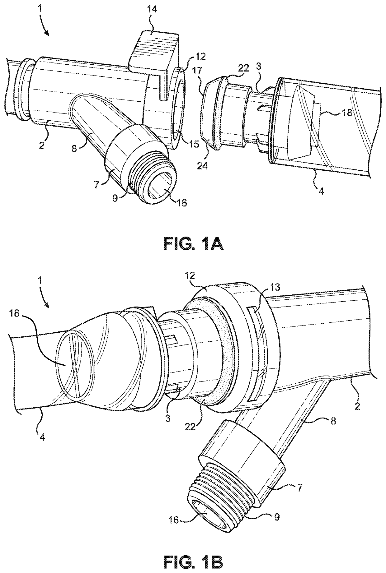
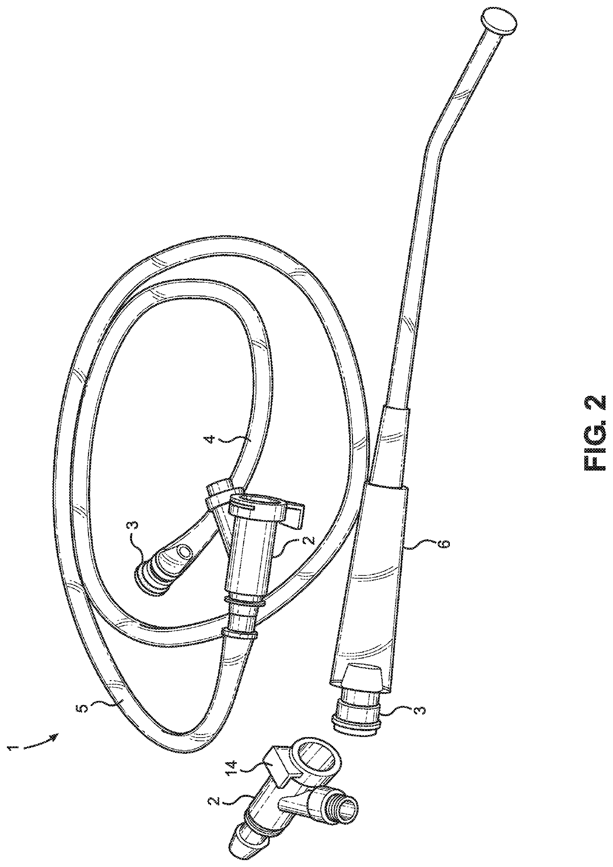
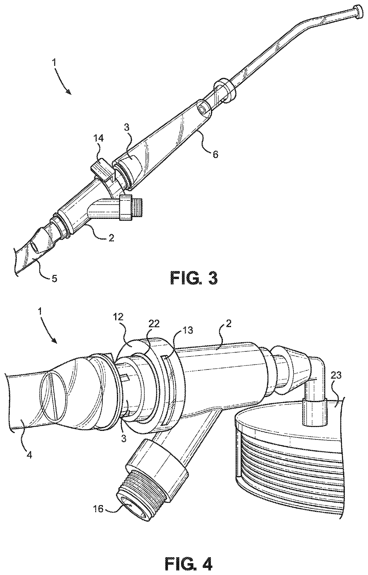
[0028]Retelling now to FIGS. 1A and 1B, there are depicted perspective views of a tube connection kit for a vacuum system, in a disconnected (FIG. 1A) and in a connected (FIG. 1B) state. A true connection kit 1 includes a female coupler 2 and a male coupler 3. The female coupler 2 comprises a forward portion 12, and the male coupler 3 comprises a forward portion 18. The forward portions (12, 18) of the female coupler 2 and the male coupler 3 each includes a forward aperture thereon. In addition, the female coupler 2 comprises a rearward portion, and the male coupler 3 includes a rearward portion 17. The rearward portions of the female coupler 2 and the male coupler 3 each includes a rearward aperture thereon. ...


PUM


Abstract

A tube connection kit for a vacuum system, and a method of clearing the vacuum system using the kit. The kit includes a female coupler and a male coupler. The male coupler includes a forward portion that connects to a first tube or a vacuum applicator, and a rearward portion that connects to a forward portion of the female coupler. A rearward portion of the female coupler connects to a second tube or a vacuum source. Interiors of the first tube or the vacuum applicator, the male coupler, the female coupler, and the second tube or the vacuum source are fluidly connected, such that a vacuum may be provided to the vacuum applicator. The female coupler includes a clearing valve that connects an exterior of the clearing valve to the interior of the female coupler, upon application of a fluid thereto, to allow clearing of the second tube.

Description

CROSS REFERENCE TO RELATED APPLICATIONS[0001]This application claims priority under 35 U.S.C. § 119(e) to U.S. Provisional Application No. 62 / 794,752 filed on Jan. 21, 2019. The above identified patent application is incorporated by reference herein in its entirety to provide continuity of disclosure.BACKGROUND OF THE INVENTION[0002]The present invention relates to a tube connection kit for connecting tubes of a vacuum system, and a method of using the kit to clear one or more tubes of the vacuum system.[0003]Surgical procedures often require the use of a vacuum system for effective clearance of biological fluids and other materials from the operation site. This is important not only for the health of the patient, but also the health of the professionals performing the surgery, as exposure to these fluids can cause transmission of blood-borne pathogens from the patient to the professional. In addition, clearing the operation site ensures a clear field of vision for the surgeon, who ...

Claims


Application Information

Patent Timeline
IPC IPC(8): F16L55/07A61M1/00F16L33/30
CPCA61M1/0035F16L55/07F16L33/30A61M39/10A61M1/743
Inventor WITHEROW, RANDY
Owner WITHEROW RANDY
Learn More