
High tension coil spring structure for bed mattress having means for preventing friction noise

a technology of high-tension coil springs and bed mattresses, which is applied in the direction of springs/dampers, mechanical devices, functional characteristics of springs/dampers, etc., can solve the problems of elasticity of exposed wiring parts, noise creation, friction noise, etc., and achieve the effect of preventing noise, reducing friction, and increasing longevity

Inactive Publication Date: 2020-07-30
AHN YOO SOO
View PDF0 Cites 3 Cited by
  • Summary
  • Abstract
  • Description
  • Claims
  • Application Information

AI Technical Summary

Benefits of technology

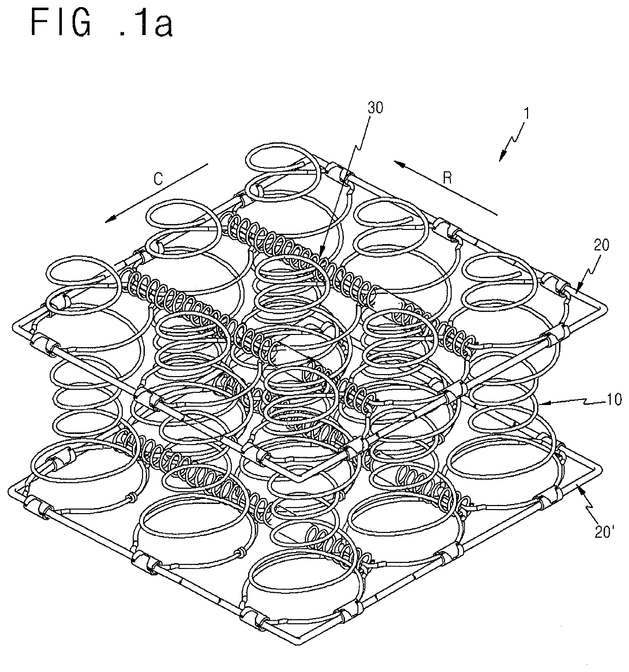
The present invention relates to a high tension coil spring structure for a bed mattress that prevents friction noise. This is achieved by providing upper and lower exposed wiring portions that extend from the body wiring portions and enclose spaces where the wiring portions move upward and downward while the coil spring structure is compressed. The resulted elasticity of the exposed wiring portions is significantly increased while noise caused by friction between the exposed wiring portions and a surrounding wiring portion is prevented. This results in improved performance of the bed mattress.

Problems solved by technology

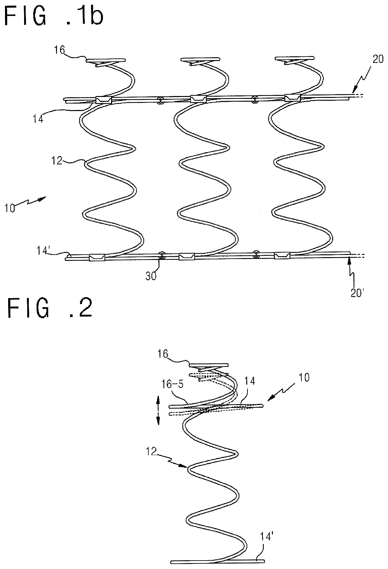
First, as shown in FIG. 2, in the process in which the coil spring 10 is compressed at the moment that the bed mattress is subjected to a load, a contact wiring portion 16-5 of the exposed wiring portion 16 abuts to the end wiring portion 14 which is positioned below while moving down. This consequently creates noise due to contact between the exposed wiring portion 16 and the end wiring portion 14.
Second, when a large load is applied to the bed mattress, the exposed wiring portion 16 of the spring assembly is compressed, and concurrently, the body wiring portion 12 is compressed at high speed. Rapid compression of the exposed wiring portion 16 increases friction between the exposed wiring portion 16 and the end wiring portion 14, thereby creating friction noise.
Third, when a load is applied to the bed mattress, the exposed wiring portion abuts to the end wiring portion while being compressed, whereby the elasticity of the exposed wiring portion is limited. Accordingly, solutions for preventing stress due to friction noise between the exposed wiring portions 16 and the end wiring portions 14 while the bed mattress is being used and for increasing the longevity of the coil spring are urgently required.
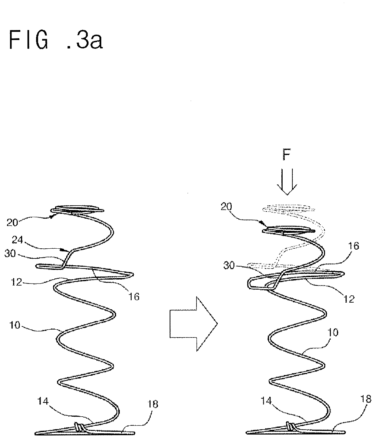
In addition, although the coil spring shown in FIG. 3A is focused on the contact-preventing end 30 which prevents frictional noise, there is a drawback in that the amount of elasticity with which the exposure wire spring 20 moves upward and downward is limited since the exposure wire spring 20 has a small number of turns.
In addition, although the coil spring shown in FIG. 3B is focused on the contact-preventing / rigidity-reinforcing ends 30 and 32 which prevent frictional noise, there is a drawback in that the amount of elasticity with which the exposure wire spring 20 moves upward and downward is limited since the exposure wire spring 20 has a small number of turns.
In addition, although the coil spring shown in FIG. 3C is focused on the concave portions 60 and 70 which prevent frictional noise, there is a drawback in that the amount of elasticity with which the exposed wiring portion 115b moves upward and downward is limited since the exposed wiring portion 115b has a small number of turns.

Method used


Image

  • High tension coil spring structure for bed mattress having means for preventing friction noise
  • High tension coil spring structure for bed mattress having means for preventing friction noise
  • High tension coil spring structure for bed mattress having means for preventing friction noise

Examples


Embodiment Construction

[0045]Reference will now be made in detail to various embodiments of the present invention, examples of which are illustrated in the accompanying drawings and described below.

[0046]As shown in FIG. 4A to FIG. 14B, the present invention provides a high tension coil spring structure for a bed mattress having means for preventing friction noise. The high tension coil spring structure includes body wiring portions 12 which are disposed regularly at preset distances from each other in the space between an upper edge member 20 and a lower edge member 20′, upper and lower end wiring portions 14 and 14′ which are provided on both ends of the body wiring portions12 and set within the range in which the upper and lower edge members 20 and 20′ are disposed, upper and lower exposed wiring portions 16 and 16′ which extend from at least one of the upper and lower end wiring portions 14 and 14′ so as to be exposed from the upper or lower edge members 20 or 20′, diameter-increasing portions A which...


PUM


Abstract

A high tension coil spring structure for a bed mattress includes spring bodies and exposed wiring portions which absorb an external load. Diameter-increasing portions (A) are formed on at least one of upper and / or lower end wiring portions (14, 14′) of body wiring portions (12), and provide spaces in which upper and / or lower exposure start wiring portions (16-5, 16-5′) move upward and downward. Rigid support ends (18) are formed on at least one of the body wiring portions (12) and upper and lower exposed wiring portions (16, 16′), and absorb a compressive load. The diameter-increasing portions and the rigid ends of the coil spring structure fundamentally prevent noise caused by friction between the exposed wiring portions and surrounding wiring portions when the exposed wiring portions are compressed and significantly increase the elasticity of the exposed wiring portions.

Description

CROSS REFERENCE TO RELATED APPLICATION[0001]The present application claims priorities from Korean Patent Application Number 10-2013-113990 filed on Sep. 25, 2013, Korean Patent Application Number 10-2013-115999 filed on Sep. 30, 2013, claiming priority from Korean Patent Application Number 10-2013-113990 filed on Sep. 25, 2013, and Korean Patent Application Number 10-2013-136458 filed on Nov. 11, 2013, claiming priorities from Korean Patent Application Number 10-2013-113990 filed on Sep. 25, 2013 and Korean Patent Application Number 10-2013-115999 filed on Sep. 30, 2013, the entire contents of which are incorporated herein for all purposes by this reference.BACKGROUND OF THE INVENTIONField of the Invention[0002]The present invention relates to a high tension coil spring structure for a bed mattress having exposed wiring portions which are formed on coil springs and cooperate with spring bodies to absorb an external load, and more particularly, to a high tension coil spring structure...

Claims


Application Information

Patent Timeline
Patent Type & Authority Applications(United States)
IPC IPC(8): A47C23/043A47C27/06F16F1/04F16F1/06F16F1/12F16F3/04
CPCA47C27/065F16F2236/04F16F1/12F16F2228/06F16F1/046F16F1/06A47C23/0438F16F3/04F16F2230/38A47C27/07
Inventor AHN, YOO SOO
Owner AHN YOO SOO
Learn More