Electrical impedance hematocrit and hba1c biosensor comprising sample plate and sample apparatus

a biosensor and electric impedance technology, applied in the field of sample measurement system, can solve the problems of red blood cells within blood samples that complicate the interpretation of blood glucose measurements using existing methods, and achieve the effects of reducing or eliminating complication, improving the accuracy of blood glucose measurements, and simplifying the interpretation of blood glucose measurements

Active Publication Date: 2020-07-30
SMARTCARE TECH
View PDF0 Cites 2 Cited by
  • Summary
  • Abstract
  • Description
  • Claims
  • Application Information

AI Technical Summary

Benefits of technology

[0011]At its most general, the invention in one aspect is a system (method and / or apparatus) to measure haematocrit of a liquid sample containing blood according to the electrical impedance (e.g., resistance and reactance) it has in response to an alternating electrical potential difference applied across the sample. The measured haematocrit maybe used to improve the accuracy of blood glucose measurements of the blood in another aspect of the invention. It has been found that applying an alternating potential difference (voltage) across such a sample results in a resistance and / or a reactance which is surprisingly responsive to haematocrit. The invention exploits this finding. The presence of red blood cells within a blood sample complicates the interpretation of blood glucose measurements using existing methods. The invention may remove or reduce that complication to enable more accurate blood glucose measurements to be made. At its most general, the invention in another aspect is a system (method and / or apparatus) to measure a level of glycated haemoglobin (HbA1c) in a liquid sample containing blood according to the electrical impedance (e.g., resistance and reactance) it has in response to an alternating electrical potential difference applied across the sample. It has been found that applying an alternating potential difference (voltage) across such a sample results in a resistance and / or a reactance which is surprisingly responsive to HbA1c of the sample. The invention exploits this finding.
[0022]Preferably, the width of the sensing gap is greater than about 90 microns and less than about 160 microns. Preferably the width of the partitioning gap is about 1.5 times the width of the sensing gap. An alternating potential difference is preferably applied across a gap between two electrodes designed to be bridged by a sample being measured. It has been found that a careful dimensioning of the sensing gap and the drive gap enhances the accuracy of haematocrit measurement greatly, and also permits HbA1c to be measured. The gap size is preferably substantially smaller than a gap size between electrodes typically employed in existing systems designed to measure blood glucose. Preferably, the sensing gap is wider than the average width of a human red blood cell, but less than the average width of two such cells.
[0050]In another of its aspects, the invention may provide sampling apparatus (e.g. measurement device) for use in performing electrical measurements on a liquid sample containing blood, the apparatus comprising: a first output terminal arranged for outputting an alternating (AC) electrical current; and a second output terminal arranged outputting a direct electrical voltage applied thereto (most preferably a substantially constant (DC) voltage); and voltage input terminals (e.g. two) each for receiving an input electrical voltage signal externally input thereto; and current input terminals (e.g. two) each for receiving an input electrical current signal externally input thereto. The apparatus may include a control unit arranged to apply an alternating electrical current to the first output terminal and concurrently to measure a first electrical voltage at the voltage input terminals resulting therefrom when a the liquid sample is in electrical series connection between the first output terminal and a current input terminal, and arranged to apply a direct voltage (most preferably a substantially constant electrical (DC) voltage) to the second output terminal and concurrently to measure a second electrical current at a current input terminal resulting therefrom when a liquid sample is in electrical series connection between the second output terminal and a current input terminal. A calculating unit of the apparatus may be arranged to calculate electrical resistance and / or reactance values for the sample using a value of the first electrical current and a value of the concurrently measured first voltage, and arranged to calculate a first calculated value representing the relative volume of red blood cells in the liquid sample (haematocrit) according to the calculated electrical resistance and / or reactance values; and to calculate a second calculated value representing an amount of glucose in the liquid sample according to both the first calculated value and the measured second electrical current, and to output the result. The measured second electrical current may be measured while the direct (DC) voltage is applied to a sample zone of a sampling plate that contains a deposit of reagent to react with free glucose in a blood sample when applied there for use in measuring a first value for blood glucose levels within a blood sample when there. The alternating current may be applied to a sample zone free of such reagent and for use in measuring haematocrit within a blood sample when there. The haematocrit value may be used to improve the first value for blood glucose levels within a blood sample.

Problems solved by technology

The presence of red blood cells within a blood sample complicates the interpretation of blood glucose measurements using existing methods.

Method used


Image

  • Electrical impedance hematocrit and hba1c biosensor comprising sample plate and sample apparatus
  • Electrical impedance hematocrit and hba1c biosensor comprising sample plate and sample apparatus
  • Electrical impedance hematocrit and hba1c biosensor comprising sample plate and sample apparatus

Examples


Embodiment Construction

[0062]In the drawings, like items are assigned like reference symbols.

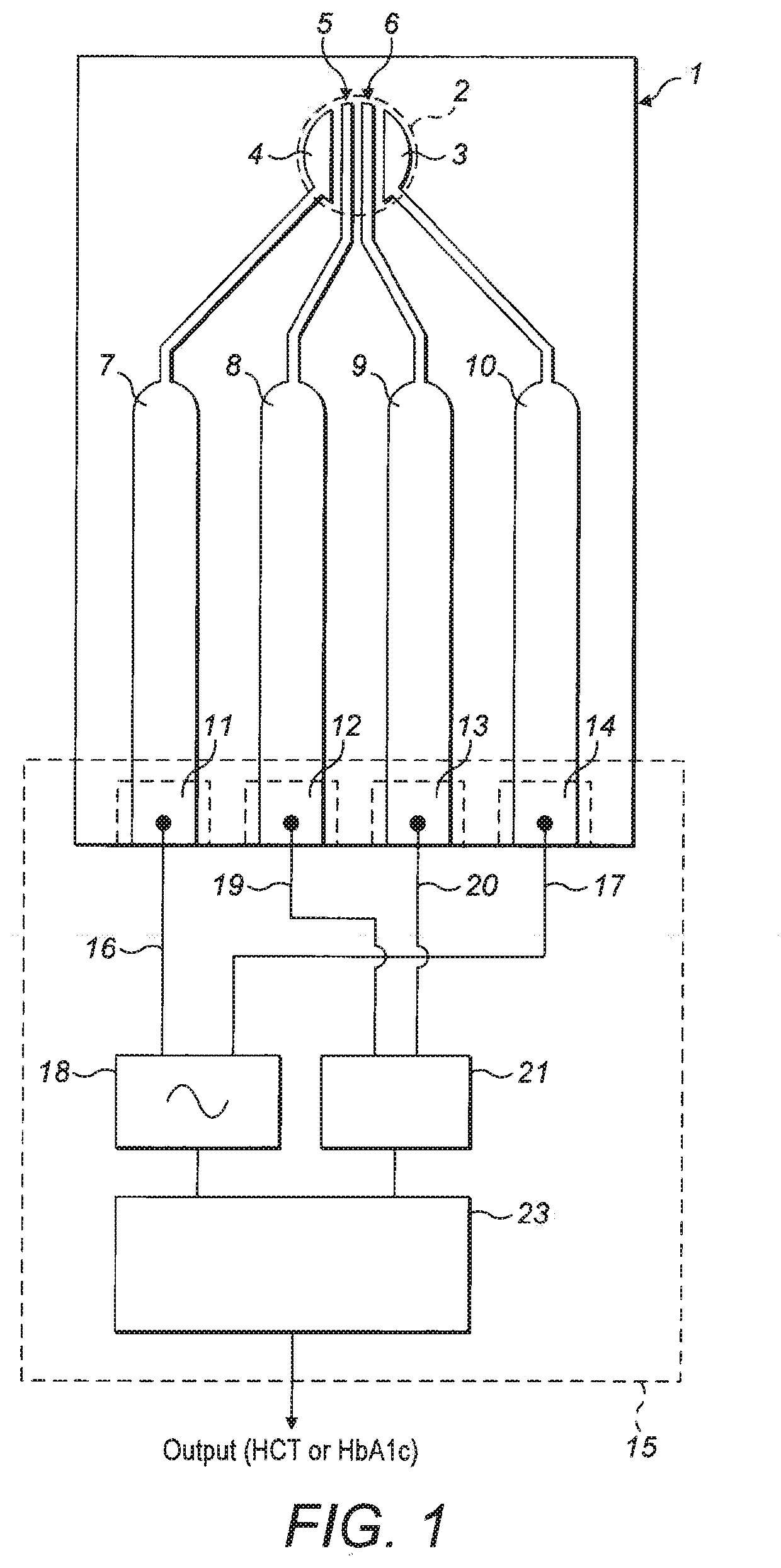
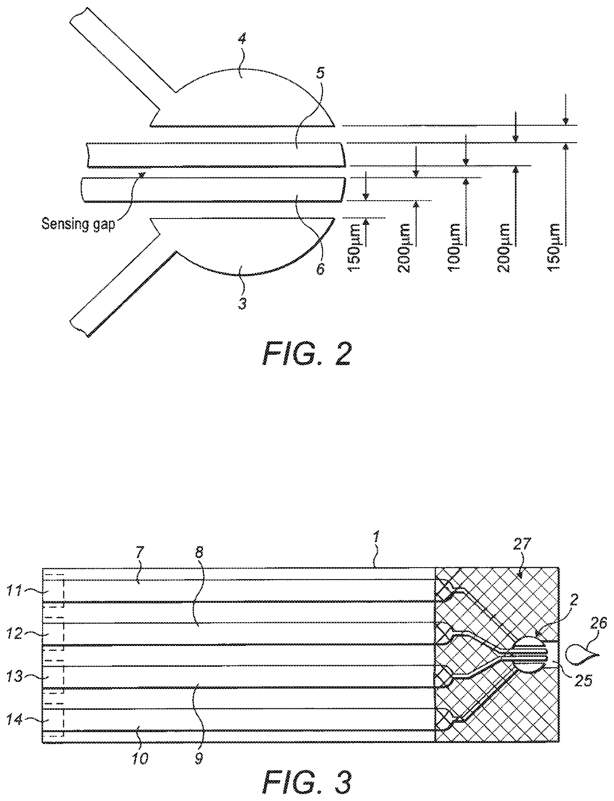
[0063]FIG. 1 shows a sampling plate (1) in the form of a strip of firm and non-conductive material (e.g. plastic) possessing a circular sample zone (2) defined by a circular recess formed within the strip for receiving a liquid blood sample. Within the sample zone there are four electrode terminals (3, 4, 5, 6) formed upon a surface of the plate forming the floor of the sample zone and exposed for contact with a received sample. The electrode terminals each comprise a layer of inert conductive material, preferably Gold.

[0064]The four electrode terminals comprise two drive electrode terminals (3, 4) each of which is in the shape of a circular segment the curved edge of which coincides with a part of the circular edge of the circular sample zone. The straight segment edge of each one of the two drive electrode terminals is parallel to and opposes the straight segment edge of the other of the two drive electrode term...


PUM

PropertyMeasurementUnit
widthaaaaaaaaaa
widthaaaaaaaaaa
areaaaaaaaaaaa

Abstract

A sampling plate (1) is provided comprising a sample zone (2) for receiving a liquid sample, and two drive electrodes (3, 4) with separate respective electrode terminals spaced by a spacing for receiving a the liquid sample within the sample zone for use in driving an electrical signal through the sample. Two sensing electrodes (5, 6) are provided with separate respective electrode terminals spaced between the electrode terminals of the two drive electrodes for use in sensing an electrical signal generated by the drive electrodes within a the sample. A sampling apparatus (15) is provided for use with the plate.

Description

RELATED APPLICATIONS[0001]This application is divisional of U.S. application Ser. No. 14 / 394,176, filed Oct. 13, 2014, which in turn is a 371 application of International Application No. PCT / GB2013 / 050957 filed Apr. 12, 2013, which claims the benefit of priority of United Kingdom Patent Application No. 1206588.4 filed Apr. 13, 2012. Each of the foregoing applications is hereby incorporated herein by reference.FIELD OF THE INVENTION[0002]The present invention relates to a sample measurement system. In particular, the present invention relates to the measurement of properties of liquid samples of (or containing) blood. In particular the invention relates to a sample measurement system for measuring certain selected properties of a liquid substrate, such as the glucose levels in a blood sample. The invention also relates to a sampling plate, a measurement device, a data carrier containing software to operate the measurement device.BACKGROUND OF THE INVENTION[0003]There is a widespread ...

Claims


Application Information

Patent Timeline
Patent Type & Authority Applications(United States)
IPC IPC(8): G01N27/327G01N27/416G01N33/49G01N33/487
CPCG01N33/492G01N33/48707G01N27/3271G01N27/416G01N27/07G01N27/3272G01N33/49
Inventor AINGER, PHILLIP J.BRYAN, MATTHEW ROBERT
Owner SMARTCARE TECH
Why Eureka
Try Eureka