Rotational Mixing and Induction Heating System and Method for Recycling Asphalt Using the Same

a technology of mixing and induction heating and asphalt, which is applied in the direction of electric/magnetic/electromagnetic heating, working up pitch/asphalt/bitumen by mixing fractions, and ways. it can solve the problem that the flight will lack the advantageous properties of some specific heating transfer flights

Active Publication Date: 2020-08-06
CRUPI FRANCESCO
View PDF0 Cites 2 Cited by
  • Summary
  • Abstract
  • Description
  • Claims
  • Application Information

AI Technical Summary

Benefits of technology

[0013]An asphalt processing system is provided. The asphalt processing system is formed from a heating system, optional additive mixing system, and induction heat source. The asphalt heating system is formed of a drum, having a tubular or conal wall, encompassing an interior and having a first end and a second end. An opening is disposed on the first end of the drum to accept asphalt cement constituents, like Reclaimed asphalt pavement (RAP), asphalt cement, aggregates, and a combination thereof, and an output at a second end of the drum to expel hot asphalt mix. In some variations, one or more bins is provided upstream of the input, meaning asphalt binder, RAP, or asphalt cement constituents like aggregates are able to fall or be transported easily to the input. The drum optionally possesses heating transfer flights disposed in the interior wall of the drum. However, other variations do not use flights, and it is contemplated that some variations of the drum lack flights and have a smooth or substantially smooth interior wall. The exterior of the heating chamber is optionally covered—partially or fully—in insulation. In some variations, the insulation is alumina-silica insulation, cellulose insulation, or combinations thereof. The insulation can be applied to a thickness of about 0.75 inch to about 2.5 inches, and thickness ranges contained therein. Nonlimiting examples are 0.75 inch, 0.85 inch, 0.9 inch, 1 inch, 1.15 inch, 1.25 inch, 1.35 inch, 1.5 inch, 1.75 inch, 2 inches, 2.25 inches, and 2.5 inches. However, one of skill in the art can readily vary the thickness of the insulation to vary heat loss from the heating drum. The heating drum wall is heated by a heating source, such as induction heating, radiant heat, convection heat, or electric heating coils. The heating drum is optionally formed of an induction-responsive material, namely ferrimagnetic, ferromagnetic, or other material that interacts with an induction heating system to generate heat. Examples of useful induction-responsive materials include iron, steel, CHT 400 steel, Fe2O3, NiOFe2O3, CuOFe2O3, MgOFe2O3, MnBi, Ni, MnSb, MnOFe2O3, steel, cobalt, NiFe, molypermalloy (molybdenum, nickel, iron alloy; 2-81-17%), sendust (aluminum, silicon, iron alloy; 6-9-85%), nickel-iron alloy (50-50%), and mixtures thereof. The thickness of the heating drum wall optionally has a thickness of between about 0.25 inch and about 2 inches, and ranges of thickness contained therein. Nonlimiting examples are 0.25 inch, 0.3 inch, 0.4 inch, 0.45 inch, 0.5 inch, 0.55 inch, 0.6 inch, 0.65 inch, −0.7 inch, 0.75 inch, 0.85 inch, 0.9 inch, 1 inch, 1.15 inch, 1.25 inch, 1.35 inch, 1.5 inch, 1.75 inch, and 2 inches. However, one of skill in the art can readily vary the thickness of the heating drum wall based on the material selected for the drum wall, the application, heating characteristics, and desired durability.

Problems solved by technology

However, other variations do not use flights, and it is contemplated that some variations of the drum lack flights and have a smooth or substantially smooth interior wall.
Other flights, such as those traditionally used in heating drums, are contemplated for use in the interior of the drum, though in many instances such flights will lack advantageous properties of some specific heating transfer flights.

Method used


Image

  • Rotational Mixing and Induction Heating System and Method for Recycling Asphalt Using the Same
  • Rotational Mixing and Induction Heating System and Method for Recycling Asphalt Using the Same
  • Rotational Mixing and Induction Heating System and Method for Recycling Asphalt Using the Same

Examples


example 1

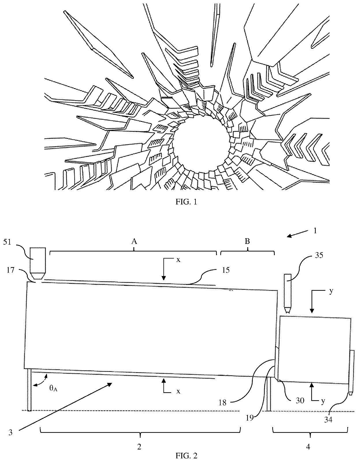
[0085]Asphalt processor 1 is composed of asphalt heating system 2, induction heating system 3, and additive mixing system 4, as seen in FIG. 2. Asphalt processor 1 is designed to heat RAP, Virgin Aggregates, virgin asphalt, a combination of RAP and virgin asphalt, and optionally additives, i.e. asphaltic material, to the requisite temperature for paving applications.

[0086]Asphalt heating system 2 is comprised of heating drum 10, oriented at angle θA. Angle θA is selected to allow asphaltic material to roll to bottom of heating drum 10 at a preferred rate of 6 to 8 inches per rotation. A decline of 7° to 10° is envisioned, however the angle can differ based on the viscosity of the asphaltic material, speed of the heating drum rotation, presence of transfer flights, gravity, humidity and other environmental factors surrounding and within the heating drum.

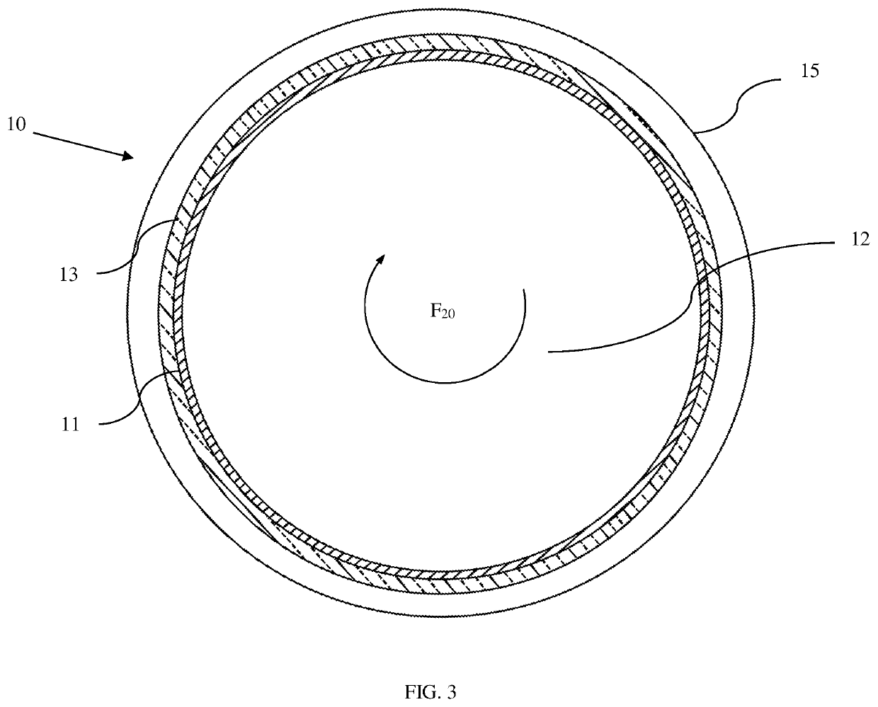
[0087]Heating drum 10 is formed of heating drum interior 12, heating drum wall 11, and wall insulation 13, as seen in FIG. 3. The he...

example 2

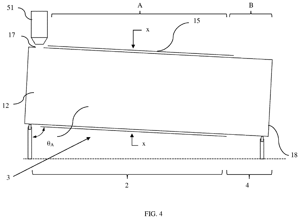
[0090]Asphalt processor 1 is designed to heat RAP, Virgin Aggregates, virgin asphalt, a combination of RAP and virgin asphalt, and optionally additives, i.e. asphaltic material, to the requisite temperature for paving applications. In this variant, asphalt heating system 2 and additive mixing system 4 are both integrated into heating drum 10, as seen in FIG. 4.

[0091]Heating drum 10 is similar to example 1, having transfer flights, an angled orientation, such as angle θA, or combination thereof to move asphaltic material to roll to bottom of heating drum 10 at a preferred rate of 6 to 8 inches per rotation. Heating drum 10 is composed of heating drum wall 11, of a induction-responsive material, and wall insulation 13, discussed in Example 1. The induction heat coils heat the drum at heating zone A, resulting in the asphalt heating to about 300° F. to 350° F. as the asphalt travels through heating zone A. The asphalt then enters heating zone B, which is unheated and serves as additive...

example 3

[0093]Asphalt processor 1 is designed to heat RAP, Virgin Aggregates, virgin asphalt, a combination of RAP and virgin asphalt, and optionally additives, i.e. asphaltic material, to different temperatures in asphalt heating system 2, seen in FIG. 5. In this variation, the asphalt processor can include additive mixing system 4 in the heating drum or have as additive mixing system 4, as seen in FIG. 4, an independent mixing system disposed downstream of the heating drum, as seen in FIG. 2. Accordingly, the systems discussed in Examples 1 and 2 can be incorporated in this variation of the invention.

[0094]Heating drum 10 is composed of heating drum wall 11, of an induction-responsive material, and wall insulation 13, discussed in Example 1. The induction heat coils heat the drum at heating zone A to between 350° F. and 400° F., resulting in the asphalt heating to about 325° F. to 375° F. as the asphalt travels through heating zone A. The asphalt then enters heating zone D, which is heate...


PUM

PropertyMeasurementUnit
temperatureaaaaaaaaaa

Abstract

An asphalt processing system is formed from a heating drum and an induction heating system. Flights move asphalt through the heating drum, which concurrently heat the asphalt along with the heating drum wall. A mixing drum can be connected to the heating drum, and include paddles or flights to move the asphalt, while concurrently mixing the material to ensure consistent temperatures through the asphalt cement. The asphalt is heating using one or more induction heating systems to quickly heat the asphalt to between 275° F. and 750° F., followed by moving the asphalt to between 275° F. and 350° F. The system can include a convection system that heats recirculated air through the heating drum. A water condenser can be employed to remove moisture during air recirculation, and reduce asphalt moisture content. The asphalt cement is optionally modified by addition of one or more rejuvenation oils. This system is particularly useful for recycled asphalt pavement, but can be used for all asphalt products.

Description

FIELD OF INVENTION[0001]The invention relates generally to a system and method for recycling used asphalt material. Specifically, the invention discloses a system and method to heat Reclaimed Asphalt Pavement (RAP), asphalt mix and virgin asphalt aggregates controllably using induction heating, while simultaneously mixing the asphalt material along the heating drum using the interior of the drum or inducted heating flights; whereby the uniform heating of the used asphalt material inhibits moisture from surging from the used asphalt material, greatly improves environmental impact with less energy consumption, concurrently reduces emissions from the heating asphalt, as no maltenes are burnt off in the processing, and also helps to maintain the structural integrity of the asphalt or rejuvenated asphalt.BACKGROUND OF INVENTION[0002]The asphalt used for paving, refining, and industrial uses is a solid or semi-solid bituminous material that is either naturally occurring, or derived from p...

Claims


Application Information

Patent Timeline
Patent Type & Authority Applications(United States)
IPC IPC(8): E01C7/26E01C19/10B01F9/06B01F15/06H05B6/10B01F29/63
CPCE01C7/26E01C19/1004E01C19/1036B01F2009/0092B01F15/065B01F15/067H05B6/10B01F9/06E01C19/05E01C19/1027H05B6/108Y02A30/30B01F2215/0422B01F2215/0472C10C1/19C10C3/005C10C1/005E01C19/10B01F29/63B01F35/92B01F35/94B01F29/40221B01F2035/99B01F2101/38
Inventor CRUPI, FRANCESCO
Owner CRUPI FRANCESCO
Why Eureka
Try Eureka