
Method and apparatus for distributed sensing

a distributed sensing and sensing technology, applied in the field of distributed optical telemetry of physical parameters, can solve the problems of difficult to distinguish, difficult to achieve, and difficult to achieve, and all of the known classes of acoustic or vibration detectors suffer from several common limitations

Active Publication Date: 2020-08-06
SENTEK INSTR
View PDF5 Cites 16 Cited by
  • Summary
  • Abstract
  • Description
  • Claims
  • Application Information

AI Technical Summary

Benefits of technology

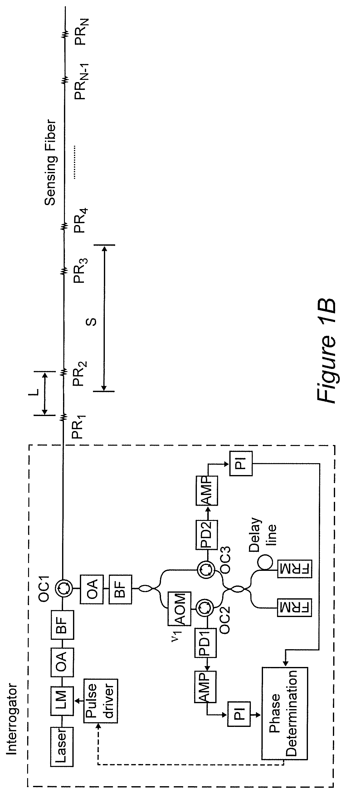
The present invention provides a fiber optic measurement technology that can measure multiple parameters like vibration, acoustic waves, temperature, strain, magnetic and / or electrical fields, as well as the location of vibration and acoustic energy along the length of a sensing or measurement fiber. This technology can use any type of optical fiber as the measurement fiber and can provide absolute phase measurement. The invention also includes an apparatus and methodology for sensing or measuring a physical parameter using a sensing or measurement optical fiber, a light source, optical elements, and an optical delay line. The interrogator version of this technology includes a light source, optical elements, and an optical delay line for measuring the response of a length of sensing or measurement optical fiber to physical parameters in its environment.

Problems solved by technology

However, such arrays engender some degree of complexity in distinguishing the responses of individual sensors in an array and tracking changes in the measured parameters.
This difficulty is particularly pronounced when seeking to measure vibration or acoustic waves.
All of these known classes of acoustic or vibration detectors suffer from several common limitations.
That is, all of these systems are limited to measurement of relative optical phase and are incapable of measuring absolute phase.
Therefore such systems are only useful for detection of dynamic events such as vibration, voice and rapid change of temperature.
Further, all of these systems are based on detection of Rayleigh backscattering which is very weak and highly irregular which limits sensitivity and often limits measurement to qualitative detection and causes significant harmonics to be present in the output signal that may compromise detection of qualities and parameters of the detected vibration or acoustic wave that may be of interest.

Method used


Image

  • Method and apparatus for distributed sensing
  • Method and apparatus for distributed sensing
  • Method and apparatus for distributed sensing

Examples


Embodiment Construction

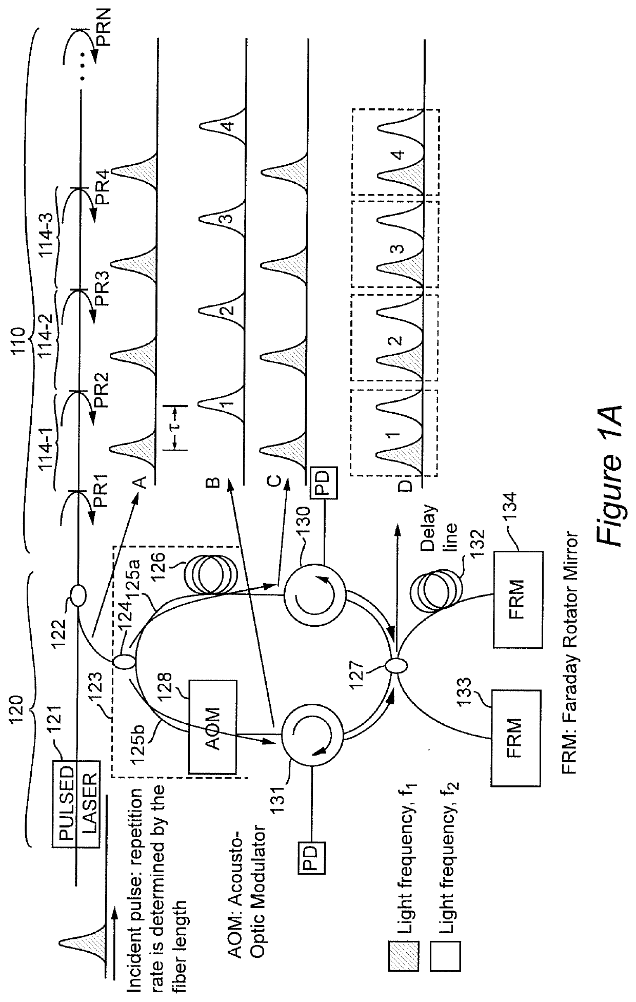
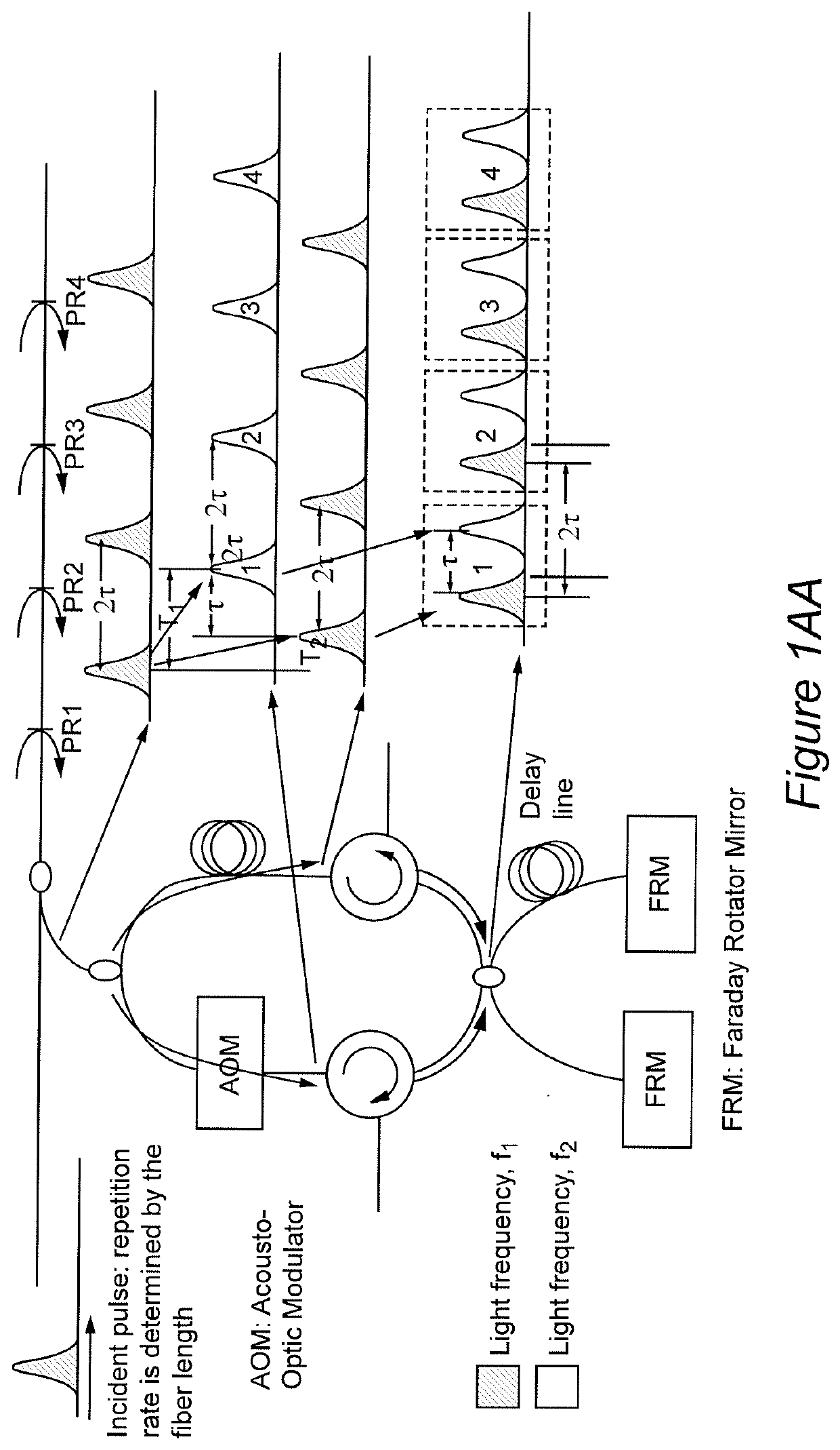
[0029]Referring now to the drawings, and more particularly to FIG. 1A, there is schematically shown a simplified and generalized embodiment of the invention including its basic elements that is useful for conveying an understanding of the basic concepts of the invention. It should be appreciated that the system illustrated in FIG. 1A has two basic portions; each portion being comprised of a particular element or combination of elements which can be respectively constituted by various optical elements having different forms as may be dictated by particular applications and which can be arranged differently in different embodiments or behaviors as will be explained in the discussion of various variant and exemplary embodiments that follows the discussion of the simplified and generalized embodiment of FIG. 1A. Other arrangements and alternative optical elements and combinations thereof that can be used to carry out the invention will also be apparent to those skilled in the art from t...


PUM


Abstract

Forming a light pulse having a plurality of time-dependent frequency components such as a chirped light pulse or a light pulse group and superposing reflected light from different portions of an optical fiber allows detection of changes in effective optical path differences due to physical parameters in the environment of the optical fiber by sensing the optical interference pattern of each light frequency and wavelength. The development of a plurality of interference patterns from each light pulse provides sufficient information for robust demodulation by known methods to produce signals having good fidelity to variations in the physical parameters of interest, particularly vibrations and acoustic waves. The location of the measured physical parameter along the optical fiber can be determined from the time difference between injecting the light pulse and detection of a reflection or Rayleigh backscattering and diffraction index of the optical fiber.

Description

DESCRIPTIONField of the Invention[0001]The present invention generally relates to remote, distributed optical telemetry of physical parameters and, more particularly, to distributed acoustic sensing capable of rapid detection and location of sources of vibration and other forms of acoustic energy as well as additional parameters and conditions.Background of the Invention[0002]The sensing of physical parameters such as temperature, pressure and strain (e.g. induced by a physical force such as flow rate) using optical elements that exhibit a dimensional change in response to those parameters has become a mature technology due to high accuracy, robustness of sensors in hostile environments and extreme conditions potentially very small sensor size for compatibility with many diverse applications and the distance over which such telemetry can be conducted using optical fibers. In recent years, arrangements have been devised to provide an array of such sensors in or on a single optical fi...

Claims


Application Information

Patent Timeline
IPC IPC(8): G01H9/00G01D5/353G02B26/04
CPCG01D5/35361G02B26/04G01H9/004
Inventor MA, LINGMEIDONG, BOWANG, ANBO
Owner SENTEK INSTR
Learn More